Operating Instructions
Modular Safety Control System MSC
10
(Translation of the original operating instructions) 2121331-04-04/19
3. Overview
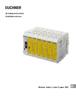
MSC is a modular safety system and comprises a base unit (MSC-CB), which can be configured using the graphic user
interface in EUCHNER Safety Designer and various extension modules that can be connected to MSC-CB via the proprietary
MSCB bus.
The base unit MSC-CB, which can also be used as a standalone device, has 8 safety inputs and 2 separate, programmable
dual-channel outputs.
Important!
Ì
The following extension modules are available:
FI8FO2
with inputs and outputs,
FI8
,
FM4
,
FI16
,
SPM0
,
SPM1
and
SPM2
only with inputs,
AC-FO2
and
AC-FO4
only with outputs, also
O8
,
O16
and
AH-FO4SO8
with monitoring outputs, as well as
AZ-FO4
and
AZ-FO4O8
with positively driv-
en safety relays. Extension modules for connection to the commonest industrial fieldbus systems
for diagnostics are also available:
CE-PR
(PROFIBUS),
CE-CO
(CanOpen),
CE-DN
(DeviceNet),
CE-EI
(ETHERNET/IP),
CE-EI2
(ETHERNET/IP-2PORT),
CE-PN
(Profinet),
CE-EC
(ETHERCAT),
CE-
MR
(Modbus RTU),
CE-MT
(Modbus/TCP).
MSC makes it possible to monitor the following safety sensors and command switches:
Optoelectronic sensors (safety light grids, scanners, safety light barriers), mechanical switches, safety mats, emergency
stop buttons, two-hand controls, which are all managed via one single, flexible device that can be expanded.
The system is only allowed to comprise a single base unit MSC-CB and a maximum of 14 electronic extension modules, of
which not more than four are allowed to be of the same type.
With 14 extension modules the system can have up to 128 inputs, 16 dual-channel safety outputs and 32 status outputs.
The modules AZ-FO4/AZ-FO4O8 have four 1-channel outputs. The greater the number of AZ-FO4/AZ-FO4O8 modules used,
the fewer dual-channel outputs are available.
The communication between the base unit (MASTER) and the extension modules (SLAVES) is via the MSCB 5-way bus (pro-
prietary bus from EUCHNER) on the rear side of every module.
In addition, 8 inputs and 16 outputs are available and can be controlled using sensors (via the fieldbus).
The number of inputs in the system can be increased using the MSC extension modules
FI8
,
FI16
and
FM4
such that more
external devices can be connected.
FM4
also provides 8 outputs of type OUT_TEST.
With the extension modules AC-FO2 and AC-FO4, the MSC system has 2 or 4 OSSD pairs to control devices connected
downstream of the MSC system.
AH-FO4SO8
is a safety module with 4 single-channel high-current safety outputs and 4 associated inputs for external device
monitoring contacts (EDM). The module is also equipped with 8 programmable signal outputs.
FI8FO2 has 8 inputs and 2 OSSD outputs.
The extension modules in the
CE
series make it possible to connect the commonest industrial fieldbus systems for diagnos-
tics and data transmission.
CE-EI
,
CE-EI2
,
CE-PN
,
CE-MT
and
CE-EC
also have an Ethernet connection.
CE-US
makes
it possible to connect devices with a USB port.
CE-CI1
,
CE-CI2
are modules in the
MSC
family that make it possible to connect
MSC-CB
to extension modules further
away (<50 m). Two
CE-CI
modules are connected at the required distance using a screened cable (can be ordered from
EUCHNER or as per the table for the cable technical data).
The following can be monitored (up to PL e) using the extension modules for speed monitoring
SPM0
,
SPM1
and
SPM2
:
Ì
Standstill, overspeed, speed range
Ì
Movement direction, rotary motion/ linear movement
Up to 4 speed limits can be defined for each logical output (axis).
Each module has two logical outputs that can be configured via EUCHNER Safety Designer. In this way up to two independent
axes can be monitored.
Summary of Contents for MSC
Page 1: ...EN Operating Instructions Installation and use Modular Safety Control System MSC ...
Page 171: ......
Page 173: ......

