Operating Instructions
Modular Safety Control System MSC
116
(Translation of the original operating instructions) 2121331-04-04/19
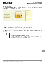
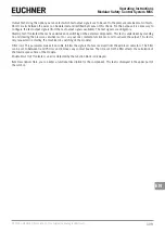
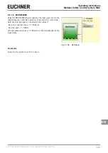
9.2.2.20. Fieldbus input (FIELDBUS INPUT)
A conventional input can be provided using this element;
the status of the input can be changed via the fieldbus.
Up to 8 virtual inputs can be provided; for each input
the bit on which the status is to be changed must be
selected.
The states are depicted on the fieldbus using one byte.
(You will find more detailed information in the fieldbus
manual on the CD ROM "EUCHNER Safety Designer".)
Figure 120: Fieldbus input
DANGER
The FIELDBUS INPUT is NOT a safety input.
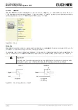
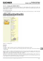
9.2.2.21. LL0 – LL1
A logic level can be supplied to the input of a component
using these elements.
LL0
Logic level 0
LL1
Logic level 1
Figure 121: Logic level
Important!
LL0 and LL1 cannot be used to deactivate the logic connections in the program.
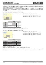
9.2.2.22. Comments
You can enter a description and position it at any point
in the diagram using this option.
Figure 122: Comments
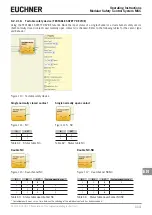
9.2.2.23. Title
Automatically adds the name of the manufacturer, the
system planner, the project name and the checksum
(CRC).
Figure 123: Title
Summary of Contents for MSC
Page 1: ...EN Operating Instructions Installation and use Modular Safety Control System MSC ...
Page 171: ......
Page 173: ......


