Operating Instructions
Modular Safety Control System MSC
88
(Translation of the original operating instructions) 2121331-04-04/19
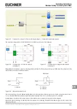
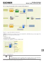
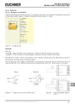
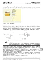
Example of usage with only the internal relay and
monitored solenoid valves
Example of usage with external contactors and
feedback
Figure 78: Examples of usage
Manual Reset: If selected, a reset can be requested each time the IN input signal drops out. Otherwise the activation of the
output follows the input conditions directly.
There are two types of reset: Manual and Monitored. On the selection of the manual reset, only the signal transition from 0
to 1 is checked. With the monitored reset the double transition from 0 to 1 and then back to 0 is checked.
Enable Status: If selected, the actual status of the relay outputs can be connected to a STATUS.
Enable external K reading: If activated, the switching times for external contactors can be read and checked:
Ì
For category 1 it is not possible to check the external contactors.
Ì
The check on the external contactors is always activated in category 4.
External K delay (ms): Maximum delay that caused by the external contactors. Using this value the maximum delay between
the switching of the internal relay and the switching of the external contacts (on activation and deactivation) can be checked.
Enable Error Out: If selected, the ERROR_OUT output is enabled.
If an error is detected on the external FBK signal,
the output changes to the logic level "high" (TRUE).
The
Error OUT
signal is reset if one of the following events occurs:
1. The system is switched off and on again.
2. The RESET MSC-CB operator is activated.
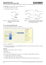
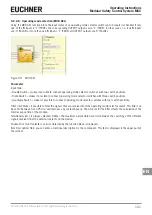
Figure 79: Example for RELAY with correct feedback
signal: in this case ERROR OUT=FALSE
Figure 80: Example for RELAY with erroneous feedback
signal (external switching time exceeded): in
this case ERROR OUT=TRUE
Summary of Contents for MSC
Page 1: ...EN Operating Instructions Installation and use Modular Safety Control System MSC ...
Page 171: ......
Page 173: ......

