111
2121331-04-04/19 (Translation of the original operating instructions)
Operating Instructions
Modular Safety Control System MSC
EN
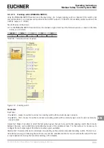
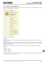
9.2.2.15. Enabling switch (ENABLING SWITCH)
Using the ENABLING SWITCH function block the input status of a 3-stage enabling switch is checked. If this switch is not
pressed (position 1) or is fully pressed (position 3), the OUTPUT output is "0" (FALSE). In the middle position (position 2) the
OUTPUT output is "1" (TRUE).
See truth tables further down.
¨
For the ENABLING SWITCH function block, the module assigned must have the firmware version as shown in the table
below, as a minimum:
MSC-CB
FI8FO2
FI8
FI16
FM4
1.0
0.4
0.4
0.4
0.0
Table 58: Firmware versions required
Figure 112: Enabling switch
Parameter
Input Type:
Ì
Double NO – makes it possible to connect an enabling switch with two normally open contacts.
Ì
Double NO + 1NC – makes it possible to connect an enabling switch with two normally open contacts and one normally
closed contact.
Output Test: Makes it possible to select the test output signals that are to be sent to the enabling switch. Short circuits
between the wires can be detected and rectified by means of this additional check. For this purpose it is necessary to
configure the test output signals (from the test output signals available).
StartUp Test: If selected, the test is undertaken on switching on the external component (enabling switch). This test is un-
dertaken by pressing and releasing the switch to carry out one complete function test and to activate the output. This test
is only requested on starting the machine (switching on the module).
Summary of Contents for MSC
Page 1: ...EN Operating Instructions Installation and use Modular Safety Control System MSC ...
Page 171: ......
Page 173: ......


