


EPSON Stylus Pro 10000/10000CF
Revision A
Disassembly & assembly
Disassembly Flow
136
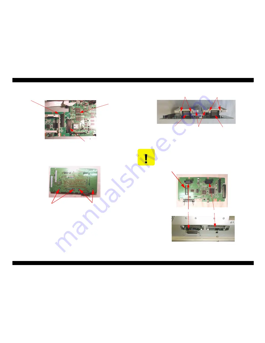
4.
Slide to the left and unplug the CN1 connection to the main board.
Figure 4-48.
5.
Unlock and push the four hooks from solder side.
Figure 4-49.
6.
Unlock the four fooks on the connector CN4 and CN5 then remove two guides.
Figure 4-50.
C362DRV board
C362MAIN board
CN1
Hook
Hook
C A U T I O N
When replacing the “Interface Board”, make sure followings.
n
Use same type of ROM on the IC2.
n
Do not exchange the mounting position of option board.
(Option board will be connect to the CN4/CN5 card slot.)
Figure 4-51.
Hook
Hook
CN5
CN4
Guide
IC2 (ROM)
CN5
CN4
Summary of Contents for Stylus Pro 10000 Series
Page 7: ...Revision Status ...
Page 8: ...Revision Issued Date Description Rev A March 30 2001 First Release ...
Page 13: ...C H A P T E R PRODUCTDESCRIPTION ...
Page 59: ...EPSON Stylus Pro 10000 10000CF Revision B Product Description Jumper Settings 59 ...
Page 60: ...C H A P T E R OPERATINGPRINCIPLES ...
Page 86: ...C H A P T E R TROUBLESHOOTING ...
Page 113: ...C H A P T E R DISASSEMBLY ASSEMBLY ...
Page 187: ...C H A P T E R ADJUSTMENT ...
Page 276: ...C H A P T E R MAINTENANCE ...
Page 289: ...C H A P T E R APPENDIX ...
Page 315: ......
Page 316: ......
Page 317: ......
Page 318: ......
Page 319: ......
Page 320: ......
Page 321: ......
Page 322: ......
Page 323: ......


