background image

GX8 Manipulator  1. Safety 


GX series  Rev.2 

81 

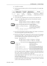
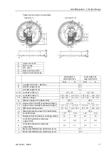
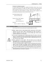
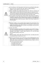
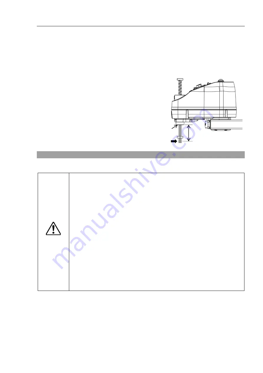
Strength of the Ball Screw Spline 

If a load exceeding the allowable value is applied to the ball screw spline, it may not work 
properly due to deformation or breakage of the shaft. If the ball screw spline is applied the 
load exceeding the allowable value, it is necessary to replace the ball screw spline unit. 
The allowable loads differ  depending on distance where the load is applied to.  For 
calculating the allowable load, see the calculation formula below. 
 
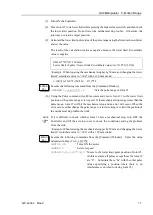
[Allowable bending moment] 

GX8: M=27,000 N

mm 


Example: If 270 N load is applied   

at 100 mm from 
the end of the spline nut 

[Moment] 

M=F

L

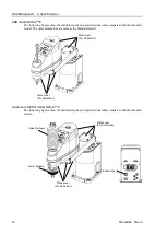
100

270

27,000 N

mm 


End of the 

spline nut 

F


L


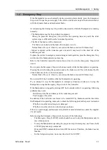
1.3    Operation Safety 

The following items are safety precautions for qualified Operator personnel: 


WARNING 


Please carefully read the 

Safety Manual

  before operating the robot system. 

Operating the robot system without understanding the safety precautions  is 

extremely hazardous and may result in serious bodily injury and/or severe 

equipment damage to the robot system. 


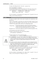
Do not enter the operating area of the Manipulator while the power to the robot 

system is turned ON. Entering the operating area with the power ON is extremely 

hazardous and may cause serious safety problems as the Manipulator may move 

even if it seems to be stopped. 


Before operating the robot system, make sure that no one is inside the 

safeguarded area. The robot system can be operated in the mode for teaching 

even when someone is inside the safeguarded area. 

The motion of the Manipulator is always in restricted (low speeds and low power) 

status to secure the safety of an operator. However, operating the robot system 

while someone is inside the safeguarded area is extremely hazardous and may 

result in serious safety problems in case that the Manipulator moves unexpectedly. 


Immediately press the Emergency Stop switch whenever the Manipulator moves 

abnormally while the robot system is operated. 


Summary of Contents for SCARA GX Series

Page 1: ...Original instructions Rev 2 EM221R5129F SCARA Robots GX series Manual ...

Page 2: ...GX series Manual Rev 2 ...

Page 3: ...GX series Rev 2 i SCARA Robots GX series Manual Rev 2 Copyright 2021 2022 SEIKO EPSON CORPORATION All rights reserved ...

Page 4: ...escribed in the manuals This manual describes possible dangers and consequences that we can foresee Be sure to comply with safety precautions on this manual to use our robot system safety and correctly TRADEMARKS Microsoft Windows and Windows logo are either registered trademarks or trademarks of Microsoft Corporation in the United States and or other countries Other brand and product names are tr...

Page 5: ...ual This section describes what you should know before reading this manual Structure of Robot System The GX series Manipulators can be used with the following combinations of Controllers and software Controller RC700 D Software EPSON RC 7 0 Ver 7 5 1B or later Setting by Using Software EPSON RC This manual contains setup procedures using the software Those sections are indicated by the symbol on t...

Page 6: ...es Manual PDF This manual describes the specifications and functions of the Manipulator The manual is primarily intended for people who design robot systems Technical information functions specifications etc required for the Manipulator installation and design Daily inspection of the Manipulator Status Code Error Code List PDF This manual contains a list of code numbers displayed on the controller...

Page 7: ...pecifications 28 2 4 How to Set the Model 28 3 Environments and Installation 29 3 1 Environmental Conditions 29 3 2 Base Table 30 3 3 Mounting Dimensions 32 3 4 From Unpacking to Installation 34 3 4 1 Precautions for the Flow from Unpacking to Installation 34 3 4 2 Table Top Mounting 36 3 4 3 Multiple Mounting 37 3 4 4 Cleanroom ESD model 38 3 5 Connecting the Cables 39 3 6 User Wires and Pneumati...

Page 8: ...e 72 GX8 Manipulator 1 Safety 79 1 1 Conventions 79 1 2 Design and Installation Safety 80 1 3 Operation Safety 81 1 4 Emergency Stop 83 1 5 Safeguard 84 1 6 Emergency Movement Without Drive Power 85 1 7 ACCELS Setting for CP Motions 86 1 8 Warning Labels 87 1 9 Response for Emergency or Malfunction 90 1 9 1 Collision 90 1 9 2 Getting body caught in Manipulator 90 2 Specifications 91 2 1 Model Numb...

Page 9: ...145 4 2 Attaching Cameras and Valves 147 4 3 Weight and Inertia Settings 149 4 3 1 Weight Setting 149 4 3 2 Inertia Setting 155 4 4 Precautions for Auto Acceleration Deceleration of Joint 3 158 5 Motion Range 161 5 1 Motion Range Setting by Pulse Range for All Joints 162 5 1 1 Max Pulse Range of Joint 1 162 5 1 2 Max Pulse Range of Joint 2 163 5 1 3 Max Pulse Range of Joint 3 164 5 1 4 Max Pulse R...

Page 10: ...t 186 2 2 Overhaul Parts Replacement 187 2 3 Greasing 187 2 4 Tightening Hexagon Socket Head Cap Bolts 190 Appendix Appendix A Specifications 193 GX4 Specifications 193 GX8 Specifications 196 Appendix B Time and Distance of Free Running in Emergency 199 GX4 Time and Distance of Free Running in Emergency 200 GX8 Time and Distance of Free Running in Emergency 206 Appendix C Time and Distance of Free...

Page 11: ...GX4 Manipulator This volume contains information for setup and operation of the Manipulators Please read this volume thoroughly before setting up and operating the Manipulators ...

Page 12: ......

Page 13: ...bling parts in a safely isolated area 1 1 Conventions Important safety considerations are indicated throughout the manual by the following symbols Be sure to read the descriptions shown with each symbol WARNING This symbol indicates that a danger of possible serious injury or death exists if the associated instructions are not followed properly WARNING This symbol indicates that a danger of possib...

Page 14: ... This product has been designed and manufactured strictly for use in a normal indoor environment Using the product in an environment that exceeds the specified environmental conditions may not only shorten the life cycle of the product but may also cause serious safety problems The robot system must be used within the installation requirements described in the manuals Using the robot system outsid...

Page 15: ...ot system without understanding the safety precautions is extremely hazardous and may result in serious bodily injury and or severe equipment damage to the robot system Do not enter the operating area of the Manipulator while the power to the robot system is turned ON Entering the operating area with the power ON is extremely hazardous and may cause serious safety problems as the Manipulator may m...

Page 16: ... the robot system CAUTION Whenever possible only one person should operate the robot system If it is necessary to operate the robot system with more than one person ensure that all people involved communicate with each other as to what they are doing and take all necessary safety precautions Joint 1 2 and 4 If the joints are operated repeatedly with the operating angle less than 5 degrees they may...

Page 17: ...ircuit Do not turn OFF the Controller while the Manipulator is operating If you attempt to stop the Manipulator in emergency situations make sure to stop the Manipulator using the Emergency Stop switch of the Controller If the Manipulator is stopped by turning OFF the Controller while it is operating following problems may occur Reduction of the life and damage of the reduction gear unit Position ...

Page 18: ...d The robot can automatically operate in unrestricted high power state For the Safeguard system do not use the circuit for E STOP For details of wiring instructions refer to the following manual RC700 D Manual 9 EMERGENCY For details of Safeguard refer to the following manual RC700 D Manual 2 7 1 Connection to EMERGENCY Connector WARNING The EMERGENCY connector on the controller has a safeguard in...

Page 19: ...int 4 The joint cannot be rotated by hand until the electromagnetic brake applied to the joint has been released Move the joint up down while pressing the brake release switch Joint 3 4 brake release switch Joint 1 rotating Joint 2 rotating Joint 3 up and down Joint 4 rotating Arm 1 Arm 2 Base Shaft The brake release switch is common to Joint 3 and Joint 4 When the brake release switch is pressed ...

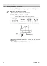
Page 20: ...ction of the life and damage of the ball screw spline Set ACCELS as follows according to the Z axis height ACCELS setting value by Z axis height and tip load Z axis height mm Tip load 3kg or less 4kg or less 0 Z 50 25000 or less 25000 or less 50 Z 100 25000 or less 100 Z 150 21500 or less Z Z axis height 0 Origin point If the Manipulator is operated in CP motion with the wrong set values make sure...

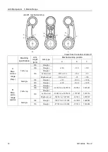
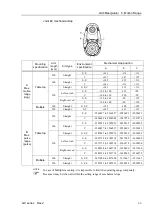
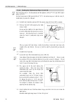
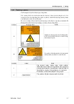
Page 21: ...ulator safely Do not tear damage or remove the warning labels Location Warning Label Note A Hazardous voltage exists while the Manipulator is ON To avoid electric shock do not touch any internal electric parts B The surface of the Manipulator is hot during and after operation and there is a risk of burns Location Information Label Note 1 The product name model name serial number information which ...

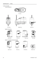
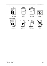
Page 22: ...bels Common Arm 2 2 Top view Table top mounting 1 B A Lateral view Front view Lateral view Back view Table top mounting Cable downward 1 B A Lateral view Front view Lateral view Bottom view Multiple mounting 1 B A Lateral view Front view Lateral view Top view ...

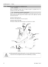
Page 23: ... a base table press the emergency stop switch to release the brake by the following method Get body caught in the arms The break is not working Move the arms manually Get body caught in the shaft The break is working Press the break release switch and move the shaft Joint 3 4 brake release switch Joint 1 rotating Joint 2 rotating Joint 3 up and down Joint 4 rotating Arm 1 Arm 2 Base Shaft CAUTION ...

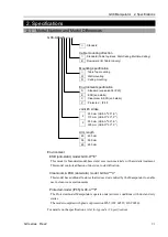
Page 24: ...nt to IP20 E ESD anti static C Cleanroom ESD anti static Joint 3 stroke 1 150 mm GX4 A 1S E 120 mm GX4 A 1C Arm length 25 250 mm 30 300 mm 35 350 mm Environment Specification ESD anti static model GX4 A 1E This model is Standard model based and uses resin materials with antistatic treatment This model controls adhesion of dust due to electrification Cleanroom ESD anti static model GX4 A 1C This mo...

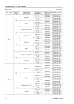
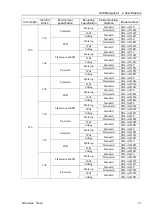
Page 25: ...20 Cleanroom ESD Table top Standard Straight GX4 A301C Downward GX4 A301CB Multiple Standard GX4 A301CM 350 150 Standard Table top Standard Straight GX4 A351S Left curved GX4 A351S L Right curved GX4 A351S R Downward Straight GX4 A351SB Left curved GX4 A351SB L Right curved GX4 A351SB R Multiple Standard Straight GX4 A351SM ESD Table top Standard Straight GX4 A351E Left curved GX4 A351E L Right cu...

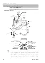
Page 26: ...ctor Joint 3 4 brake release switch Joint 1 rotating Joint 3 up and down Joint 4 rotating Arm 1 Arm 2 Base Shaft Indicating lamp Joint 2 rotating Cable duct Conduit tube The brake release switch is common to Joint 3 and Joint 4 When the brake release switch is pressed in emergency mode the brakes for Joint 3 and Joint 4 are released Make sure to turn OFF the Controller and inform others that you a...

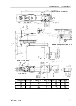
Page 27: ...1S E a 250 300 350 b 120 170 220 c 560 585 610 d 30 36 36 e 146 143 143 Details of B Position of mechanical stop Space for connector 1 mm flat cut Conical hole ø3 90 Max ø11 through hole shaft diameter mechanical stop diameter Details of A Calibration point position of Joints 3 and 4 ...

Page 28: ...r dimensions are same as the Standard model Plate cover For Anti static Plate cover For Anti static Plate cover For Anti static Cleanroom ESD model GX4 A 1C The following figures show the additional parts and specifications when compared with the Standard model Upper bellows Lower bellows Plate cover For Anti static Plate cover For Anti static Exhaust port Plate cover For Anti static ...

Page 29: ... 350 b 120 170 220 c 560 585 610 d 30 36 36 e 146 143 143 Details of B Position of mechanical stop Space for connector 1 mm flat cut Conical hole ø3 90 Details of A Calibration point position of Joints 3 and 4 Max ø11 through hole shaft diameter mechanicalstop diameter bellows outer diameter ...

Page 30: ... and down Joint 4 rotating Arm 1 Arm 2 Base Shaft Indicating lamp Joint 2 rotating Cable duct Conduit tube Face plate Manipulator serial No The brake release switch is common to Joint 3 and Joint 4 When the brake release switch is pressed in emergency mode the brakes for Joint 3 and Joint 4 are released Make sure to turn OFF the Controller and inform others that you are working before the maintena...

Page 31: ...51SB EB a 250 300 350 b 120 170 220 c 560 585 610 d 30 36 36 e 146 143 143 Details of B Position of mechanical stop Space for connector 1 mm flat cut Conical hole ø3 90 shaft diameter Max ø11 through hole mechanical stop diameter Details of A Calibration point position of Joints 3 and 4 ...

Page 32: ...he Standard model The outer dimensions are same as the Standard model Plate cover For Anti static Plate cover For Anti static Plate cover For Anti static Cleanroom ESD model GX4 A 1CB The outer dimensions are same as the Standard model Upper bellows Lower bellows Plate cover For Anti static Plate cover For Anti static Exhaust port Plate cover For Anti static ...

Page 33: ...00 350 b 120 170 220 c 560 585 610 d 30 36 36 e 146 143 143 Details of B Position of mechanical stop Space for connector 1 mm flat cut Conical hole ø3 90 Details of A Calibration point position of Joints 3 and 4 Max ø11 through hole shaft diameter mechanicalstop diameter bellows outer diameter ...

Page 34: ...or ø6 mm pneumatic tube Indicating lamp Fitting blue for ø4 mm pneumatic tube Fitting blue for ø6 mm pneumatic tube Conduit tube The brake release switch is common to Joint 3 and Joint 4 When the brake release switch is pressed in emergency mode the brakes for Joint 3 and Joint 4 are released Make sure to turn OFF the Controller and inform others that you are working before the maintenance work Pe...

Page 35: ...X4 A301SM EM GX4 A351SM EM a 300 350 b 170 220 c 475 500 Space for connector Position of mechanical stop 1 mm flat cut Conical hole ø3 90 Max ø11 through hole shaft diameter mechanicalstop diameter Details of A Calibration point position of Joints 3 and 4 ...

Page 36: ...fications when compared with the Standard model The outer dimensions are same as the Standard model Plate cover For Anti static Cleanroom ESD model GX4 A 1CM The following figures show the additional parts and specifications when compared with the Standard model Upper bellows Lower bellows Plate cover For Anti static Exhaust port ...

Page 37: ... GX4 A351CM a 300 350 b 170 220 c 475 500 Space for connector Position of mechanical stop 1 mm flat cut Conical hole ø3 90 Max ø11 through hole shaft diameter mechanical stop diameter bellows outer diameter Details of A Calibration point position of Joints 3 and 4 ...

Page 38: ...del be sure to set the Manipulator model properly Improper setting of the Manipulator model may result in abnormal or no operation of the Manipulator and or cause safety problems If the custom specifications number MT is described on MODEL of the signature label S N label the Manipulator has custom specifications The custom specifications may require a different configuration procedure Check the c...

Page 39: ... salinity metal powder or other contaminants Keep away from flammable or corrosive solvents and gases Keep away from water Keep away from shock or vibration Keep away from sources of electric noise Keep away from explosive area Keep away from a large quantity of radiation Manipulators are not suitable for operation in harsh environments When using Manipulators in inadequate environments that do no...

Page 40: ...e Controller manual CAUTION When cleaning the Manipulator do not rub it strongly with alcohol or benzene It may lose luster on the coated face 3 2 Base Table A base table for anchoring the Manipulator is not supplied Please make or obtain the base table for your Manipulator The shape and size of the base table differs depending on the use of the robot system For your reference we list some Manipul...

Page 41: ...llation surface is improper the base may be damaged or the robot may not fully show its performance When using a leveler to adjust the height of the base table use a screw with M16 diameter or more If you are passing cables through the holes on the base table see the figures below unit mm M C cable Power connector Signal connector M C cable hood Signal connector 54 35 49 11 82 44 Power connector s...

Page 42: ...de of the arm set the maximum range including the space that they may reach Be sure to allow for the following extra spaces in addition to the space required for mounting the Manipulator Controller and peripheral equipment Space for teaching Space for maintenance and inspection Space for cables The minimum bend radius of the power cable is 60 mm When installing the cable be sure to maintain suffic...

Page 43: ...r 3 Environments and Installation GX series Rev 2 33 Table top mounting Straight arm GX4 A351 GX4 A301 GX4 A251 Table top mounting Curved arm GX4 A351 R GX4 A351 L Multiple mounting Straight arm GX4 A351 M GX4 A301 M ...

Page 44: ...t hands or fingers caught To carry the Manipulator have two or more people to work on it and secure the Manipulator to the delivery equipment or hold the bottom of Arm 1 and bottom of the base by hand When holding the bottom of the base by hand be very careful not to get your hands or fingers caught Table top mounting GX4 A251 approx 15 kg 33 lb GX4 A301 approx 15 kg 33 lb GX4 A351 approx 16 kg 35...

Page 45: ...n GX series Rev 2 35 The following sections describe the installation of the Standard Manipulator and ESD model 3 4 2 Table Top Mounting 3 4 3 Multiple Mounting For Cleanroom ESD Manipulator refer to the following section 3 4 4 Cleanroom ESD model ...

Page 46: ...packing box Be careful not to fall the Manipulator as the Manipulator is not secured when you take it from the packing box The joints can be rotated by the Manipulator own weight Be careful not to get hands or fingers caught 2 Secure the base to the base table with four bolts Be sure to use washers Use bolts with specifications conforming to ISO898 1 property class 10 9 or 12 9 Tightening torque 3...

Page 47: ...ase table for installing the Multiple mounting Manipulator so that it does not touch any cable and conduit tube connected to the Manipulator The recommended installation patterns are as follows Side Ceiling This section describes the recommended wall installation method 1 With the arm extended take the manipulator from the packing box Be careful not to fall the Manipulator as the Manipulator is no...

Page 48: ...the dust on the Manipulator with a little alcohol or distilled water on a lint free cloth 4 Carry the Manipulator in the clean room 5 Refer to the mounting procedure of each Manipulator model and install the Manipulator 3 4 2 Table Top Mounting 3 4 3 Multiple Mounting 6 Connect an exhaust tube to the exhaust port For the Manipulator of Cleanroom ESD model use it with an exhaust system For details ...

Page 49: ...t in damage to the cables disconnection and or contact failure Damaged cables disconnection or contact failure is extremely hazardous and may result in electric shock and or improper function of the robot system Grounding the manipulator is done by connecting with the controller Ensure that the controller is grounded and the cables are correctly connected If the ground wire is improperly connected...

Page 50: ... attached to the housing 1 Open the lock plates on both sides of the M C cable housing 2 Insert the M C cable hood thoroughly 3 Close the lock plates on both sides of the M C cable housing 1 2 3 Minimum distance required for insertion and removal Distance when wearing Connection of M C cable and Manipulator Connect the power connector and signal connector of the M C cable to the Controller respect...

Page 51: ...h the same number are wired between the connector on the base side and the connector on the Arm 2 side in the manipulator Attached connector for user wiring Model number Manufacturer Standard Note D sub 15 pin Connector 61801524823 Würth Elektronik Solder type 2 Clamp hood 61801525311 Fitted setscrew 4 40 UNC 2 Equivalent to 8pin RJ45 Cat 5e A commercially available Ethernet cable can be connected...

Page 52: ...ue for ø4 mm pneumatic Fitting blue for ø6 mm pneumatic Fitting white for ø6 mm pneumatic User connector 15 pin D sub connector Base side Table top mounting Ethernet connector Housing for M C cable Fitting blue for ø4 mm pneumatic tube Fitting blue for ø6 mm pneumatic tube Fitting white for ø6 mm pneumatic tube User connector 15 pin D sub connector ...

Page 53: ...blue for ø4 mm pneumatic tube Fitting blue for ø6 mm pneumatic tube Fitting white for ø6 mm pneumatic User connector 15 pin D sub connector Base side Multiple mounting Ethernet connector Fitting white for ø6 mm pneumatic tube User connector 15 pin D sub connector Housing for M C cable Fitting blue for ø6 mm pneumatic tube Fitting blue for ø4 mm pneumatic tube ...

Page 54: ... the Manipulator to prevent falling Removing the anchor bolts without support may result in a fall of the Manipulator and then get hands fingers or feet caught To carry the Manipulator have two or more people to work on it and secure the Manipulator to the delivery equipment or hold the bottom of Arm 1 and bottom of the base by hand When holding the bottom of the base by hand be very careful not t...

Page 55: ...6 kg 35lbs 1 Turn OFF all power and remove the wiring and piping connected to the Manipulator If you are using the variable mechanical stops for the Joints 1 and 2 and the operating angle is limited change the mechanical stop position same as the factory configured For details refer to 5 2 Motion Range Setting by Mechanical Stops 2 Cover the arm with a sheet so that the arm will not be damaged Ref...

Page 56: ...eries Rev 2 3 Hold the bottom of Arm 1 by hand to unscrew the anchor bolts Then remove the Manipulator from the base table GX4 A251 Center of gravity Center of gravity GX4 A301 Center of gravity Center of gravity GX4 A351 Center of gravity Center of gravity ...

Page 57: ...t the Manipulator and then remove the anchor bolts Removing the anchor bolts without supporting is extremely hazardous and may result in fall of the Manipulator 1 Turn OFF all power and remove the wiring and piping connected to the Manipulator If you are using the variable mechanical stops for the Joints 1 and 2 and the operating angle is limited change the mechanical stop position same as the fac...

Page 58: ...nd Installation 48 GX series Rev 2 3 Hold the bottom of Arm 1 by hand to unscrew the anchor bolts Then remove the Manipulator from the wall GX4 A301 M Center of gravity Center of gravity GX4 A351 M Center of gravity Center of gravity ...

Page 59: ...e when the power to the robot system is turned OFF Improper connection of the wires and or pneumatic tubes may damage the robot system and or work piece as the work piece is released when the Emergency Stop switch is pressed I O outputs are configured at the factory so that they are automatically shut off 0 by power disconnection the Emergency Stop switch or the safety features of the robot system...

Page 60: ...s being pressed The switch releases the brake of Joints 3 and 4 simultaneously Brake release switch The shaft may be lowered by the weight of an end effector etc Be careful of the shaft falling and rotating while the brake release switch is being pressed because the shaft may be lowered by the weight of an end effector Layouts When you operate the manipulator with an end effector the end effector ...

Page 61: ...cables to the screw holes of the Arm 2 top and cable duct covered part use them within the following allowable load 200g assuming the distance from mounting surface to center of gravity is 100mm Arm 2 side common unit mm Top view Bottom view Table top mounting 141 4 M4 depth 8 202 5 15 2 M4 depth 8 15 339 8 15 54 59 7 199 5 From the base mounting surface From the base mounting surface 11 6 15 11 6...

Page 62: ...rors excessive shock insufficient function of the Manipulator and or shorten the life cycle of parts mechanisms The acceptable weight capacity end effector and work piece in GX4 series is 2 kg at the default rating and 4 kg at the maximum When the load weight of the end effector and work piece exceeds the rating change the setting of Weight parameter After the setting is changed the maximum accele...

Page 63: ...Parameter Shaft Weight of camera M 1kg W 1kg L2 130 mm LM 180 mm Joint 2 Automatic speed setting by Weight Standard mode GX4 A25 GX4 A30 GX4 A35 140 120 100 80 60 40 20 0 1 2 3 4 kg 100 Weight setting 100 The percentages on the graph are ratios based on the speed at the rated 2kg setting is 100 Boost mode GX4 A25 GX4 A30 GX4 A35 140 120 100 80 60 40 20 0 1 2 3 4 kg 100 Weight setting 100 The perce...

Page 64: ...sed on the acceleration deceleration at the rated 2kg setting is 100 GX4 A30 140 120 100 80 60 40 20 0 1 2 3 4 kg 100 Weight setting 45 124 136 78 The percentages on the graph are ratios based on the acceleration deceleration at the rated 2kg setting being 100 GX4 A35 140 120 100 80 60 40 20 0 1 2 3 4 kg 100 Weight setting 60 112 125 80 The percentages on the graph are ratios based on the accelera...

Page 65: ...celeration at the rated 2kg setting is 100 GX4 A30 140 120 100 80 60 40 20 0 1 2 3 4 kg 100 Weight setting 58 112 123 78 The percentages on the graph are ratios based on the acceleration deceleration at the rated 2kg setting is 100 GX4 A35 140 120 100 80 60 40 20 0 1 2 3 4 kg 100 Weight setting 60 112 125 80 The percentages on the graph are ratios based on the acceleration deceleration at the rate...

Page 66: ...f parts mechanisms The acceptable moment of inertia of load for a GX4 series Manipulator is 0 005 kg m2 at the default rating and 0 05 kg m2 at the maximum When the moment of inertia of the load exceeds the rating change the setting of the moment of inertia parameter of the Inertia command After the setting is changed the maximum acceleration deceleration speed of Joint 4 at PTP motion correspondi...

Page 67: ...ufficient function of the Manipulator and or shorten the life cycle of parts mechanisms The acceptable eccentric quantity of load in GX4 series is 0 mm at the default rating and 150 mm at the maximum When the eccentric quantity of load exceeds the rating change the setting of eccentric quantity parameter of Inertia command After the setting is changed the maximum acceleration deceleration speed of...

Page 68: ...g the moment of inertia Refer to the following examples of formulas to calculate the moment of inertia of load end effector with work piece The moment of inertia of the entire load is calculated by the sum of each part a b and c Work piece b Work piece c End effector a Joint 3 shaft Rotation center Moment of inertia of end effector a Moment of inertia of work piece b Moment of inertia of work piec...

Page 69: ... of Joint 3 When you move the Manipulator in horizontal PTP motion with Joint 3 Z at a high position the motion time will be faster When Joint 3 gets below a certain point then auto acceleration deceleration is used to reduce acceleration deceleration The higher the position of the shaft is the faster the motion acceleration deceleration is However it takes more time to move Joint 3 up and down Ad...

Page 70: ... acceleration deceleration at the shaft upper limit position is 100 GX4 A30 100 80 60 40 20 0 30 60 90 120 150 mm 78 44 44 100 100 22 Shaft height The percentages on the graph are ratios based on the acceleration deceleration at the shaft upper limit position is 100 GX4 A35 100 80 60 40 20 0 30 60 90 120 150 mm 91 71 80 100 100 60 Shaft height The percentages on the graph are ratios based on the a...

Page 71: ...40 20 0 30 60 90 120 150 mm 100 Shaft height 100 100 The percentages on the graph are ratios based on the acceleration deceleration at the shaft upper limit position is 100 When moving the Manipulator horizontally while the shaft is being lowered it may cause over shoot at the time of final positioning NOTE ...

Page 72: ...ed due to layout efficiency or safety follow the descriptions in 5 1 to 5 3 to set the range 5 1 Motion Range Setting by Pulse Range for All Joints Pulses are the basic unit of Manipulator motion The motion range of the Manipulator is controlled by the pulse range between the pulse lower limit and upper limit of each joint Pulse values are read from the encoder output of the servo motor For the ma...

Page 73: ... defined as the positive and the clockwise pulse value is defined as the negative Y X 0 pulse B B A A Table top mounting Arm length mm Arm type Straight Left curved Right curved A Max motion range deg 250 140 300 350 165 110 110 165 B Max pulse range pulse 250 1456356 to 6699236 300 350 2184534 to 5825423 582543 to 7427414 Multiple mounting Arm length mm Arm type Straight A Max motion range deg 30...

Page 74: ...top mounting Arm length mm Environment specification Arm type Straight Left curved Right curved A Max motion range deg 250 S E 141 C 137 300 S E 142 C 141 350 S E 142 165 to 120 120 to 165 C 160 to 120 120 to 160 B Max pulse range pulse 250 S E 2566827 to 2566827 C 2494009 to 2494009 300 S E 2585032 to 2585032 C 2566827 to 2566827 350 S E 2585032 to 2585032 3003734 to 2184534 2184534 to 3003734 C ...

Page 75: ...06667 0 to 1365334 For the Cleanroom ESD model GX4 A 1C the motion range set with the Joint 3 mechanical stop cannot be changed 5 1 4 Max Pulse Range of Joint 4 The 0 zero pulse position of Joint 4 is the position where the flat near the end of the shaft faces toward the end of Arm 2 It is the same regardless of the Arm 2 direction With the 0 pulse as a starting point the counterclockwise pulse va...

Page 76: ...ical stop Joint 3 mechanical stop upper limit mechanical stop Joint 2 mechanical stop stable Joint 1 mechanical stop variable Joint 2 mechanical stop variable Joint 1 mechanical stop stable Do not move the upper limit mechanical stop Multiple mounting Joint 1 mechanical stop stable Joint 1 mechanical stop variable The different mechanical stop positions from Table Top mounting are indicated for Mu...

Page 77: ...anged at low speeds until it reaches the positions of the minimum and maximum pulse range Make sure that the arm does not hit the mechanical stops Check the position of the mechanical stop and the motion range you set Example Using GX4 A 1S The angle of Joint 1 is set from 110 degrees to 110 degrees The angle of Joint 2 is set from 120 degrees to 120 degrees EPSON RC Execute the following commands...

Page 78: ...Straight 350 Straight Left curved 165 to 110 150 95 Right curved 110 to 165 95 150 Multiple 300 Straight 115 102 6 102 6 350 Straight 120 103 5 103 5 B Max pulse range pulse Table top 250 Straight 1456356 to 6699236 582542 5825423 300 Straight 350 Straight Left curved 2184534 to 5825423 1747627 5388516 Right curved 582543 to 7427414 145636 6990507 Multiple 300 Straight 728178 to 5971058 367002 560...

Page 79: ...lse range pulse Table top 250 Straight S E 2566827 to 2566827 2020693 2020693 C 2494009 to 2494009 1947876 1947876 300 Straight S E 2585032 to 2585032 2038898 2038898 C 2566827 to 2566827 2020693 2020693 350 Straight S E C 2585032 to 2585032 2038898 2038898 Left curved S E 3003734 to 2184534 2457600 1638400 C 2912712 to 2184534 2366578 1638400 Right curved S E 2184534 to 3003734 1638400 2457600 C ...

Page 80: ... sure to hold the shaft by hand while pressing the button 3 Turn OFF the Controller 4 Loosen the lower limit mechanical stop screw M3 10 A mechanical stop is mounted on both the top and bottom of Joint 3 However only the position of the lower limit mechanical stop on the top can be changed Do not remove the upper limit mechanical stop on the bottom because the calibration point of Joint 3 is speci...

Page 81: ...and Go Pulse command move Joint 3 to the lower limit position of the pulse range at low speed If the mechanical stop range is less than the pulse range Joint 3 will hit the mechanical stop and an error will occur When the error occurs either change the pulse range to a lower setting or extend the position of the mechanical stop within the limit If it is difficult to check whether Joint 3 hits a me...

Page 82: ... Window 5 4 Standard Motion Range The following motion range diagrams show the standard maximum specification When each Joint motor is under servo control the center of the Manipulator shaft s lowest point moves in the areas shown in the figure Area limited by mechanical stop is the area where the center of shaft s lowest point can be moved when each joint motor is not under servo control Mechanic...

Page 83: ...n range 87 95 105 107 142 g Motion range of the back side 221 9 260 2 298 5 h Angle to the Joint 1 mechanical stop 2 5 i Angle to the Joint 2 mechanical stop 1 5 2 4 1 6 2 5 j Mechanical stop area 84 92 99 103 137 k Mechanical stop area of the back side 225 2 264 9 304 5 m Joint 3 stroke 150 120 150 120 150 120 n Distance from the base mounting surface 26 30 26 30 26 30 p Joint 3 mechanical stop a...

Page 84: ...otion range 121 142 g Motion range of the back side 210 8 240 h Angle to the Joint 1 mechanical stop 4 0 i Angle to the Joint 2 mechanical stop 2 5 j Mechanical stop area 115 137 k Mechanical stop area of the back side 212 4 253 m Joint 3 stroke 150 120 150 120 n Distance from the base mounting surface 138 172 138 172 p Joint 3 mechanical stop area upper limit 6 5 10 5 6 5 10 5 q Joint 3 mechanica...

Page 85: ... f Motion range 100 192 107 192 192 100 192 107 g Motion range of the back side 342 5 342 5 h h Angle to the Joint 1 mechanical stop 3 0 7 0 7 0 3 0 i i Angle to the Joint 2 mechanical stop 2 8 3 8 3 5 3 8 3 8 2 8 3 8 3 5 j j Mechanical stop area 97 183 102 183 183 97 183 102 k Mechanical stop area of the back side 345 2 345 2 m Joint 3 stroke 150 120 150 120 n Distance from the base mounting surf...

Page 86: ...GX4 Manipulator 5 Motion Range 76 GX series Rev 2 ...

Page 87: ...GX8 Manipulator This volume contains information for setup and operation of the Manipulators Please read this volume thoroughly before setting up and operating the Manipulators ...

Page 88: ......

Page 89: ...bling parts in a safely isolated area 1 1 Conventions Important safety considerations are indicated throughout the manual by the following symbols Be sure to read the descriptions shown with each symbol WARNING This symbol indicates that a danger of possible serious injury or death exists if the associated instructions are not followed properly WARNING This symbol indicates that a danger of possib...

Page 90: ...s product has been designed and manufactured strictly for use in a normal indoor environment Using the product in an environment that exceeds the specified environmental conditions may not only shorten the life cycle of the product but may also cause serious safety problems The robot system must be used within the installation requirements described in the manuals Using the robot system outside of...

Page 91: ... robot system without understanding the safety precautions is extremely hazardous and may result in serious bodily injury and or severe equipment damage to the robot system Do not enter the operating area of the Manipulator while the power to the robot system is turned ON Entering the operating area with the power ON is extremely hazardous and may cause serious safety problems as the Manipulator m...

Page 92: ... the robot system CAUTION Whenever possible only one person should operate the robot system If it is necessary to operate the robot system with more than one person ensure that all people involved communicate with each other as to what they are doing and take all necessary safety precautions Joint 1 2 and 4 If the joints are operated repeatedly with the operating angle less than 5 degrees they may...

Page 93: ...tion makes the brakes work This will shorten the life of the brakes due to the worn friction plates Normal brake life cycle About 2 years when the brakes are used 100 times day Do not turn OFF the Controller while the Manipulator is operating If you attempt to stop the Manipulator in emergency situations make sure to stop the Manipulator using the Emergency Stop switch of the Controller If the Man...

Page 94: ...able circuit is engaged Safeguard closed The robot can automatically operate in unrestricted high power state For the safeguard do not use the E STOP circuit For details of wiring instructions refer to the following manual RC700 D Manual 9 EMERGENCY For details of Safeguard refer to the following manual RC700 D Manual 2 7 1 Connection to EMERGENCY Connector WARNING The EMERGENCY connector on the c...

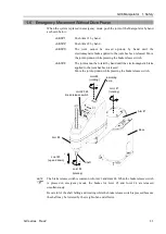
Page 95: ...int cannot be rotated by hand until the electromagnetic brake applied to the joint has been released Move the joint up down while pressing the brake release switch Joint 2 rotating Joint 1 rotating Arm 2 Joint 3 4 brake release switch Indicating lamp Base Arm 1 Shaft Joint 3 up and down Joint 4 rotating The brake release switch is common to Joint 3 and Joint 4 When the brake release switch is pres...

Page 96: ...of the ball screw spline Set ACCELS as follows according to the Z axis height ACCELS setting value by Z axis position and tip load Z axis height mm Tip load 4kg or less 6kg or less 8kg or less 0 Z 100 25000 or less 25000 or less 23500 or less 100 Z 200 23000 or less 16000 or less 200 Z 330 16000 or less 11500 or less Z axis height 0 Origin point Z If the Manipulator is operated in CP motion with t...

Page 97: ...pulator safely Do not tear damage or remove the warning labels Location Warning Label NOTE A Hazardous voltage exists while the Manipulator is ON To avoid electric shock do not touch any internal electric parts B The surface of the Manipulator is hot during and after operation and there is a risk of burns Location Label Note 1 The product name model name serial number information which laws and re...

Page 98: ...2 Location of Labels Common Arm 2 E 2 Top view B Front view Lateral view Back view Table top mounting 1 B A Lateral view Front view Lateral view Back view Table top mounting Cable downward 1 B A Lateral view Front view Lateral view Bottom view ...

Page 99: ...GX8 Manipulator 1 Safety GX series Rev 2 89 Wall mounting 1 B A Lateral view Front view Lateral view Top view Ceiling mounting 1 B A Lateral view Front view Lateral view Back view ...

Page 100: ...e emergency stop switch to release the brake on the subject arm and then move the arm by hand Get body caught in the arms The break is not working Move the arms manually Get body caught in the shafts The break is working Press the break release switch and move the shafts Joint 2 rotating Joint 1 rotating Arm 2 Joint 3 4 brake release switch Indicating lamp Base Arm 1 Shaft Joint 3 up and down Join...

Page 101: ... P 3 330 mm GX8 A 3S E 300 mm GX8 A 3C P Arm length 45 450 mm 55 550 mm 65 650 mm Environment ESD anti static model GX8 A E This model is Standard model based and uses resin materials with antistatic treatment This model controls adhesion of dust due to electrification Cleanroom ESD anti static model GX8 A C This model has additional features that reduce dust emitted by the Manipulator to enable u...

Page 102: ...ble top Standard GX8 A453S Downward GX8 A453SB Wall Standard GX8 A453SW Ceiling GX8 A453SR ESD Table top Standard GX8 A453E Downward GX8 A453EB Wall Standard GX8 A453EW Ceiling GX8 A453ER 300 Cleanroom ESD Table top Standard GX8 A453C Downward GX8 A453CB Wall Standard GX8 A453CW Ceiling GX8 A453CR Protected Table top Standard GX8 A453P Downward GX8 A453PB Wall Standard GX8 A453PW Ceiling GX8 A453P...

Page 103: ...p Standard GX8 A652S Downward GX8 A652SB Wall Standard GX8 A652SW Ceiling GX8 A652SR ESD Table top Standard GX8 A652E Downward GX8 A652EB Wall Standard GX8 A652EW Ceiling GX8 A652ER 170 Cleanroom ESD Table top Standard GX8 A652C Downward GX8 A652CB Wall Standard GX8 A652CW Ceiling GX8 A652CR Protected Table top Standard GX8 A652P Downward GX8 A652PB Wall Standard GX8 A652PW Ceiling GX8 A652PR 330 ...

Page 104: ...c tube Joint 2 rotating Joint 1 rotating Arm 2 Joint 3 4 brake release switch Indicating lamp Base Arm 1 Shaft Joint 3 up and down Joint 4 rotating The brake release switch affects both Joints 3 and 4 When the brake release switch is pressed in emergency mode the brakes for both Joints 3 and 4 are released simultaneously For GX8 1 Joint 4 has no brake on it While the LED lamp is on the current is ...

Page 105: ...E a 200 200 300 300 400 400 b 200 330 200 330 200 330 c 99 31 99 31 99 31 d 709 834 709 834 709 834 e 16 6 11 6 16 6 11 6 16 6 11 6 Mount eyebolt when transporting Details of B 1 mm flat cut Conical hole ø4 90 Details of A Calibration point position of Joints 3 and 4 Position of mechanical stop Space for connector Section ...

Page 106: ... the Standard model The outer dimensions are same as the Standard model Plate cover For Anti static Plate cover For Anti static Cleanroom ESD model GX8 A C The following figures show the additional parts and specifications when compared with the Standard model Upper bellows Lower bellows Plate cover For Anti static Plate cover For Anti static Exhaust port ...

Page 107: ...0 300 300 400 400 b 170 300 170 300 170 300 c 96 34 96 34 96 34 d 791 5 910 5 791 5 910 5 791 5 910 5 e 13 6 8 6 13 6 8 6 13 6 8 6 Mount eyebolt when transporting Details of B 1 mm flat cut Conical hole ø4 90 Details of A Calibration point position of Joints 3 and 4 Position of mechanical stop Space for connector Section ...

Page 108: ...t User connectors with cover Protected model Fittings with cover Protected model Joint 3 4 brake release switch Protected model User connectors with cover Protected model Exhaust port with cover Protected model Fittings with cover Protected model For Protected model all the screws used for outer parts are stainless steel screws Excluding the screw used for mechanical stop The housing for M C cable...

Page 109: ...0 300 300 400 400 b 170 300 170 300 170 300 c 96 34 96 34 96 34 d 791 5 910 5 791 5 910 5 791 5 910 5 e 13 6 8 6 13 6 8 6 13 6 8 6 Mount eyebolt when transporting Details of B 1 mm flat cut Conical hole ø4 90 Details of A Calibration point position of Joints 3 and 4 Position of mechanical stop Section Space for connector ...

Page 110: ... mm pneumatic tube User connector Ethernet connector Housing for M C cable User connector 15 pin D sub connector User connector 9 pin D sub connector The brake release switch is common to Joint 3 and Joint 4 When the brake release switch is pressed in emergency mode the brakes for Joint 3 and Joint 4 are released simultaneously Make sure to turn OFF the Controller and inform others that you are wo...

Page 111: ...X8 A553SB EB GX8 A652SB EB GX8 A653SB EB a 200 200 300 300 400 400 b 200 330 200 330 200 330 c 99 31 99 31 99 31 d 709 834 709 834 709 834 e 16 6 11 6 16 6 11 6 16 6 11 6 Details of B 1 mm flat cut Conical hole ø4 90 Details of A Calibration point position of Joints 3 and 4 Position of mechanical stop Space for connector Section ...

Page 112: ... the Standard model The outer dimensions are same as the Standard model Plate cover For Anti static Plate cover For Anti static Cleanroom ESD model GX8 A CB The following figures show the additional parts and specifications when compared with the Standard model Upper bellows Lower bellows Plate cover For Anti static Plate cover For Anti static Exhaust port ...

Page 113: ...53CB GX8 A652CB GX8 A653CB a 200 200 300 300 400 400 b 170 300 170 300 170 300 c 96 34 96 34 96 34 d 791 5 910 5 791 5 910 5 791 5 910 5 e 13 6 8 6 13 6 8 6 13 6 8 6 Details of B 1 mm flat cut Conical hole ø4 90 Details of A Calibration point position of Joints 3 and 4 Position of mechanical stop Space for connector Section ...

Page 114: ...nt User connectors with cover Protected model Fittings with cover Protected model Exhaust port with cover Protected model User connectors with cover Protected model Fittings with cover Protected model Joint 3 4 brake release switch Protected model For Protected model all the screws used for outer parts are stainless steel screws Excluding the screw used for mechanical stop The housing for M C cabl...

Page 115: ...53PB GX8 A652PB GX8 A653PB a 200 200 300 300 400 400 b 170 300 170 300 170 300 c 96 34 96 34 96 34 d 791 5 910 5 791 5 910 5 791 5 910 5 e 13 6 8 6 13 6 8 6 13 6 8 6 Details of B 1 mm flat cut Conical hole ø4 90 Details of A Calibration point position of Joints 3 and 4 Position of mechanical stop Section Space for connector ...

Page 116: ... Ethernet connector Housing for M C cable User connector 15 pin D sub connector User connector 9 pin D sub connector Joint 3 4 brake release switch The brake release switch affects both Joints 3 and 4 When the brake release switch is pressed in emergency mode the brakes for both Joints 3 and 4 are released simultaneously Make sure to turn OFF the Controller and inform others that you are working b...

Page 117: ...X8 A652SW EW GX8 A653SW EW a 200 200 300 300 400 400 b 200 330 200 330 200 330 c 16 141 16 141 16 141 d 410 535 410 535 410 535 e 16 6 11 6 16 6 11 6 16 6 11 6 Details of B Position of mechanical stop Space for connector 1 mm flat cut Conical hole ø4 90 Details of A Calibration point position of Joints 3 and 4 ...

Page 118: ... the Standard model The outer dimensions are same as the Standard model Plate cover For Anti static Plate cover For Anti static Cleanroom ESD model GX8 A CW The following figures show the additional parts and specifications when compared with the Standard model Upper bellows Lower bellows Plate cover For Anti static Plate cover For Anti static Exhaust port ...

Page 119: ... A653CW a 200 200 300 300 400 400 b 170 300 170 300 170 300 c 98 5 223 5 98 5 223 5 98 5 223 5 d 525 5 650 5 525 5 650 5 525 5 650 5 e 13 6 8 6 13 6 8 6 13 6 8 6 Details of B Position of mechanical stop Space for connector 1 mm flat cut Conical hole ø4 90 Details of A Calibration point position of Joints 3 and 4 ...

Page 120: ...nt User connectors with cover Protected model Fittings with cover Protected model User connectors with cover Protected model Fittings with cover Protected model Joint 3 4 brake release switch Protected model Exhaust port with cover Protected model For Protected model all the screws used for outer parts are stainless steel screws Excluding the screw used for mechanical stop The housing for M C cabl...

Page 121: ... A653PW a 200 200 300 300 400 400 b 170 300 170 300 170 300 c 98 5 223 5 98 5 223 5 98 5 223 5 d 525 5 650 5 525 5 650 5 525 5 650 5 e 13 6 8 6 13 6 8 6 13 6 8 6 Details of B Position of mechanical stop Space for connector 1 mm flat cut Conical hole ø4 90 Details of A Calibration point position of Joints 3 and 4 ...

Page 122: ...ic tube Joint 2 rotating Joint 1 rotating Arm 2 Joint 3 4 brake release switch Indicating lamp Base Arm 1 Shaft Joint 3 up and down Joint 4 rotating The brake release switch affects both Joints 3 and 4 When the brake release switch is pressed in emergency mode the brakes for both Joints 3 and 4 are released simultaneously Make sure to turn OFF the Controller and inform others that you are working ...

Page 123: ...652SR ER GX8 A653SR ER a 200 200 300 300 400 400 b 200 330 200 330 200 330 c 16 141 16 141 16 141 d 410 535 410 535 410 535 e 16 6 11 6 16 6 11 6 16 6 11 6 Details of B Section Position of mechanical stop Space for connector 1 mm flat cut Conical hole ø4 90 Details of A Calibration point position of Joints 3 and 4 ...

Page 124: ... the Standard model The outer dimensions are same as the Standard model Plate cover For Anti static Plate cover For Anti static Cleanroom ESD model GX8 A CR The following figures show the additional parts and specifications when compared with the Standard model Upper bellows Lower bellows Plate cover For Anti static Plate cover For Anti static Exhaust port ...

Page 125: ...3CR a 200 200 300 300 400 400 b 170 300 170 300 170 300 c 98 5 223 5 98 5 223 5 98 5 223 5 d 525 5 650 5 525 5 650 5 525 5 650 5 e 13 6 8 6 13 6 8 6 13 6 8 6 Details of B Section Position of mechanical stop Space for connector 1 mm flat cut Conical hole ø4 90 Details of A Calibration point position of Joints 3 and 4 ...

Page 126: ... Plate cover for oil resistant User connectors with cover Protected model Fittings with cover Protected model Joint 3 4 brake release switch Protected model User connectors with cover Protected model Exhaust port with cover Protected model Fittings with cover Protected model For Protected model all the screws used for outer parts are stainless steel screws Excluding the screw used for mechanical s...

Page 127: ...3PR a 200 200 300 300 400 400 b 170 300 170 300 170 300 c 98 5 223 5 98 5 223 5 98 5 223 5 d 525 5 650 5 525 5 650 5 525 5 650 5 e 13 6 8 6 13 6 8 6 13 6 8 6 Details of B Section Position of mechanical stop Space for connector 1 mm flat cut Conical hole ø4 90 Details of A Calibration point position of Joints 3 and 4 ...

Page 128: ...del be sure to set the Manipulator model properly Improper setting of the Manipulator model may result in abnormal or no operation of the Manipulator and or cause safety problems If the custom specifications number MT is described on MODEL of the signature label S N label the Manipulator has custom specifications The custom specifications may require a different configuration procedure check the c...

Page 129: ...efer to the Controller manual When the product is used in a low temperature environment around the minimum temperature of the product specification or when the product is suspended for a long time on holidays or at night a collision detection error may occur due to the large resistance of the drive unit immediately after the start of operation In such a case it is recommended to warm up for about ...

Page 130: ...tance However if your requirements specify that the Manipulator must withstand certain kinds of oil please contact the supplier of your region Rapid change in temperature and humidity can cause condensation inside the Manipulator If your requirements specify that the Manipulator handles food please contact the supplier of your region to check whether the Manipulator will damage the food or not The...

Page 131: ...000 N Max Vertical reaction force 1500 N The threaded holes required for mounting the Table top mounting and Ceiling mounting Manipulator are M8 or M10 The threaded holes required for mounting the Wall mounting Manipulator are M8 Use mounting bolts with specifications conforming to ISO898 1 property class 10 9 or 12 9 For dimensions refer to 2 2 Part Names and Outer Dimensions and 3 3 Mounting Dim...

Page 132: ...cable hood Signal connector 54 35 49 11 82 44 Power connector straight 83 76 Power connector L shaped 35 Do not remove the M C cables from the Manipulator For environmental conditions regarding space when placing the Controller on the base table refer to the Controller manual WARNING To ensure safety a safeguard must be installed for the robot system For details on the safeguard refer to 1 5 Safeg...

Page 133: ...eplace the Joint 1 motor while the Manipulator is secured to the base and improves maintainability Joint 1 reduction gear unit Section SS SS Joint 1 motor A Minimum space of base table required to remove Joint 1 motor and reduction gear unit B Minimum hole of base table required to remove Joint 1 motor and reduction gear unit ...

Page 134: ...e of the arm set the maximum range including the space that they may reach Be sure to allow for the following extra spaces in addition to the space required for mounting the Manipulator Controller and peripheral equipment Space for teaching Space for maintenance and inspection Space for cables The minimum bend radius of the power cable is 60 mm When installing the cable be sure to maintain suffici...

Page 135: ...GX8 Manipulator 3 Environments and Installation GX series Rev 2 125 Table top mounting GX8 A65 GX8 A55 GX8 A45 Wall mounting GX8 A65 W GX8 A55 W GX8 A45 W Ceiling mounting GX8 A65 R GX8 A55 R GX8 A45 R ...

Page 136: ... can fall Be careful not to get hands or fingers caught The arm is secured with a wire tie etc Leave the wire tie secured until you finish the installation so as not to get hands or fingers caught To carry the Manipulator have two or more people to work on it and secure the Manipulator to the delivery equipment or hold the areas indicated in gray in the figure bottom of Arm 1 and bottom of the bas...

Page 137: ...or Protected model refer to each section 3 4 5 Cleanroom ESD model 3 4 6 Protected model Follow the procedure below to transport the Manipulator by lifting 1 Attach the eyebolt to the upper part of the base of the Manipulator 2 Put the Manipulator arm in the extended position 3 Allow the lifting belt to be fixed to Arm 2 Use the metal part of the shaded area in the figure below as a guide to preve...

Page 138: ...h specifications conforming to ISO898 1 Property Class 10 9 or 12 9 Tightening torque M8 32 0 N m 326 kgf cm M10 58 0 N m 626 kgf cm 4 M8 40 Spring washer Plane washer Screw hole depth 20 mm or more 20mm 2 Using nippers cut off the wire tie binding the shaft and arm retaining bracket on the base Washer M6 Bolt M4 35 Sheet Bolt M8 20 Washer M12 Wire tie 3 Remove the bolts securing the wire ties rem...

Page 139: ...e Manipulator and then secure the anchor bolts Removing the support without securing the anchor bolts properly is extremely hazardous and may result in fall of the Manipulator 1 With the arm extended take the Manipulator from the packing box The joints can be rotated by the Manipulator own weight Be careful not to get hands or fingers caught 2 Secure the base to the wall with six bolts Be sure to ...

Page 140: ...pulator and then secure the anchor bolts Removing the support without securing the anchor bolts properly is extremely hazardous and may result in fall of the Manipulator 1 With the arm extended take the Manipulator from the packing box The joints can be rotated by the Manipulator own weight Be careful not to get hands or fingers caught 2 Secure the base to the ceiling with four bolts Be sure to us...

Page 141: ...h an exhaust system For details of the exhaust system refer to Appendix A Specifications 3 4 6 Protected model Refer to the mounting procedure of each Manipulator model and install the Manipulator 3 4 2 Table Top Mounting 3 4 3 Wall Mounting 3 4 4 Ceiling Mounting When the Manipulator is a Protected model be aware of the followings WARNING Connect the M C cable connector to the Manipulator immedia...

Page 142: ...e controller is grounded and the cables are correctly connected If the ground wire is improperly connected to ground it may result in the fire or electric shock CAUTION When connecting the Manipulator to the Controller make sure that the serial numbers on each equipment match Improper connection between the Manipulator and Controller may not only cause improper function of the robot system but als...

Page 143: ...o the housing 1 Open the lock plates on both sides of the M C cable housing 2 Insert the M C cable hood thoroughly 3 Close the lock plates on both sides of the M C cable housing 1 2 3 Minimum distance required for insertion and removal Distance when wearing Connection of M C cable and Manipulator Connect the power connector and signal connector of the M C cable to the Controller respectively Power...

Page 144: ...ulator pins with the same number are wired between the connector on the base side and the connector on the Arm 2 side in the manipulator Recommended connector to connect to the Manipulator Standard model ESD model Cleanroom ESD model Model number Standard Manufacturer Note D sub 15 pin Connector 61801524823 Solder type Würth Elektronik 2 Clamp Hood 61801525311 Fitted setscrew 4 40 UNC 2 D sub 9 pi...

Page 145: ...pulator is a Protected model be aware of the followings CAUTION Be sure to use IP65 compliant wires and tubes when using the Manipulator under special environmental conditions adverse condition with dust and oily smoke Wiring and piping with the except Protected model may result in electric shock and or malfunction of the robot system as it cannot ensure IP65 Be sure to attach the cap on the user ...

Page 146: ...p mounting Fitting white for ø6 mm pneumatic tube User connector 15 pin D sub connector User connector 9 pin D sub connector Fitting blue for ø4 mm pneumatic tube Fitting white for ø4 mm pneumatic tube Housing for M C cable Ethernet connector Fitting blue for ø6 mm pneumatic tube Base side Wall mounting Cable downward Fitting white for ø6 mm pneumatic tube User connector 15 pin D sub connector Use...

Page 147: ... pneumatic tube Fitting white for ø4 mm pneumatic tube Housing for M C cable Ethernet connector Fitting blue for ø6 mm pneumatic tube Base side Ceiling mounting Fitting white for ø6 mm pneumatic tube User connector 15 pin D sub connector User connector 9 pin D sub connector Fitting blue for ø4 mm pneumatic tube Fitting white for ø4 mm pneumatic tube Housing for M C cable Ethernet connector Fitting...

Page 148: ... to prevent falling Removing the anchor bolts without support may result in a fall of the Manipulator and then get hands fingers or feet caught To carry the Manipulator have two or more people to work on it and secure the Manipulator to the delivery equipment or hold the bottom of Arm 1 and bottom of the base by hand When holding the bottom of the base by hand be very careful not to get your hands...

Page 149: ...urn OFF all power and remove the wiring and piping connected to the Manipulator If you are using the variable mechanical stops for the Joints 1 and 2 and the operating angle is limited change the mechanical stop position same as the factory configured For details refer to 5 2 Motion Range Setting by Mechanical Stops 2 Cover the arm with a sheet so that the arm will not be damaged Tie the lower end...

Page 150: ...on 140 GX series Rev 2 3 Hold the bottom of Arm 1 by hand to unscrew the anchor bolts Then remove the Manipulator from the base table GX8 A45 Center of gravity GX8 A55 Center of gravity Center of gravity GX8 A65 Center of gravity Center of gravity ...

Page 151: ...d then remove the anchor bolts Removing the anchor bolts without supporting is extremely hazardous and may result in fall of the Manipulator 1 Turn OFF all power and remove the wiring and piping connected to the Manipulator If you are using the variable mechanical stops for the Joints 1 and 2 and the operating angle is limited change the mechanical stop position same as the factory configured For ...

Page 152: ...nts and Installation 142 GX series Rev 2 3 Hold the bottom of Arm 1 by hand to unscrew the anchor bolts Then remove the Manipulator from the wall GX8 A45 W Center of gravity GX8 A55 W Center of gravity GX8 A65 W Center of gravity ...

Page 153: ...r and then remove the anchor bolts Removing the anchor bolts without supporting is extremely hazardous and may result in fall of the Manipulator 1 Turn OFF all power and remove the wiring and piping connected to the Manipulator If you are using the variable mechanical stops for the Joints 1 and 2 and the operating angle is limited change the mechanical stop position same as the factory configured ...

Page 154: ...tallation 144 GX series Rev 2 3 Hold the bottom of Arm 1 by hand to unscrew the anchor bolts Then remove the Manipulator from the ceiling GX8 A45 R Center of gravity Center of gravity GX8 A55 R Center of gravity GX8 A65 R Center of gravity ...

Page 155: ...c tubes properly so that the gripper does not release the work piece when the power to the robot system is turned OFF Improper connection of the wires and or pneumatic tubes may damage the robot system and or work piece as the work piece is released when the Emergency Stop switch is pressed I O outputs are configured at the factory so that they are automatically shut off 0 by power disconnection t...

Page 156: ...is being pressed The switch releases the brake of Joints 3 and 4 simultaneously Brake release switch The shaft may be lowered by the weight of an end effector etc Be careful of the shaft falling and rotating while the brake release switch is being pressed because the shaft may be lowered by the weight of an end effector Layouts When you operate the manipulator with an end effector the end effector...

Page 157: ... the screw holes of the Arm 2 top and cable duct covered part use them within the following allowable load With any external wiring option 250g assuming the distance from mounting surface to center of gravity is 100mm Without any external wiring option 750g assuming the distance from mounting surface to center of gravity is 100mm Arm 2 side common unit mm Bottom view Table top mounting 283 4 M5 ta...

Page 158: ...48 GX series Rev 2 Wall mounting 49 4 M5 tap face 54 2 M8 tap face Root C1 GX8 A PW 4 M4 depth6 Other than GX8 A PW 4 M4 depth7 5 Ceiling mounting 283 4 M5 tap face 288 2 M8 tap face Root C1 GX8 A PR 4 M4 depth6 Other than GX8 A PR 4 M4 depth7 5 ...

Page 159: ...e of parts mechanisms The acceptable weight capacity end effector and work piece in GX8 series is 4 kg at the default rating and 8 kg at the maximum When the load weight of the end effector and work piece exceeds the rating change the setting of Weight parameter After the setting is changed the maximum acceleration deceleration speed of the robot system at PTP motion corresponding to the Weight Pa...

Page 160: ... kg camera is attached to the end of the GX8 Arm 2 350 mm away from the rotation center of Joint 2 with a load weight of 2 kg M 1 L2 250 LM 350 WM 1 3502 2502 1 96 2 round up W WM 2 2 4 Enter 4 for the Weight Parameter Shaft LM 350 L2 250 Weight of camera M 1kg W 2kg Joint 2 ...

Page 161: ...the graph are ratios based on the speed at the rated 4kg setting is 100 GX8 A55 140 120 100 80 60 40 20 0 1 2 3 4 5 6 7 8 kg 100 85 70 Weight setting The percentages on the graph are ratios based on the speed at the rated 4kg setting is 100 GX8 A65 140 120 100 80 60 40 20 0 1 2 3 4 5 6 7 8 kg 100 80 70 Weight setting The percentages on the graph are ratios based on the speed at the rated 4kg setti...

Page 162: ...os based on the speed at the rated 4kg setting is 100 GX8 A55 140 120 100 80 60 40 20 0 1 2 3 4 5 6 7 8 kg 100 85 70 Weight setting The percentages on the graph are ratios based on the speed at the rated 4kg setting is 100 GX8 A65 140 120 100 80 60 40 20 0 1 2 3 4 5 6 7 8 kg 100 80 70 Weight setting The percentages on the graph are ratios based on the speed at the rated 4kg setting is 100 ...

Page 163: ... on the acceleration deceleration at the rated 4kg setting is 100 GX8 A55 140 120 100 80 60 40 20 0 1 2 3 4 5 6 7 8 kg 100 85 55 120 120 120 Weight setting The percentages on the graph are ratios based on the acceleration deceleration at the rated 4kg setting is 100 GX8 A65 140 120 100 80 60 40 20 0 1 2 3 4 5 6 7 8 kg 100 80 55 120 120 120 Weight setting The percentages on the graph are ratios bas...

Page 164: ...ation at the rated 4kg setting is 100 GX8 A55 140 120 100 80 60 40 20 0 1 2 3 4 5 6 7 8 kg 100 85 49 136 136 136 Weight setting The percentages on the graph are ratios based on the acceleration deceleration at the rated 4kg setting is 100 GX8 A65 140 120 100 80 60 40 20 0 1 2 3 4 5 6 7 8 kg 100 62 43 120 120 120 Weight setting The percentages on the graph are ratios based on the acceleration decel...

Page 165: ...chanisms The acceptable moment of inertia of load for a GX8 series Manipulator is 0 01 kg m2 at the default rating and 0 16 kg m2 at the maximum When the moment of inertia of the load exceeds the rating change the setting of the moment of inertia parameter of the Inertia command After the setting is changed the maximum acceleration deceleration speed of Joint 4 at PTP motion corresponding to the m...

Page 166: ...f eccentric quantity parameter of Inertia command After the setting is changed the maximum acceleration deceleration speed of the Manipulator at PTP motion corresponding to the eccentric quantity is set automatically Position of load s center of gravity Rotation center Eccentric quantity 150 mm or less Eccentric Quantity Eccentric quantity of load on the shaft The eccentric quantity of load weight...

Page 167: ...r a Joint 3 shaft Rotation center Moment of inertia of end effector a Moment of inertia of work piece b Moment of inertia of work piece c Whole moment of inertia The methods for calculating the moment of inertia for a b and c are shown below Calculate the total moment of inertia using the basic formulas a Moment of inertia of a rectangular parallelepiped h b L m Rectangular parallelepiped s center...

Page 168: ...ill be faster When Joint 3 gets below a certain point then auto acceleration deceleration is used to reduce acceleration deceleration The higher the position of the shaft is the faster the motion acceleration deceleration is However it takes more time to move Joint 3 up and down Adjust the position of Joint 3 for the Manipulator motion after considering the relation between the current position an...

Page 169: ...leration deceleration at the shaft upper limit position is 100 GX8 A55 100 80 60 40 20 0 50 100 150 200 250 300 350 mm 90 75 15 100 100 40 Shaft height The percentages on the graph are ratios based on the acceleration deceleration at the shaft upper limit position is 100 GX8 A65 100 80 60 40 20 0 50 100 150 200 250 300 350 mm 80 60 10 100 100 41 Shaft height The percentages on the graph are ratios...

Page 170: ...50 200 250 300 350 mm 78 44 11 100 100 22 Shaft height The percentages on the graph are ratios based on the acceleration deceleration at the shaft upper limit position is 100 GX8 A65 100 80 60 40 20 0 50 100 150 200 250 300 350 mm 64 39 14 100 100 25 Shaft height The percentages on the graph are ratios based on the acceleration deceleration at the shaft upper limit position is 100 When moving the ...

Page 171: ...et at the same time The motion range is preset at the factory as explained in 5 4 Standard Motion Range There are three methods for setting the motion range described as follows 1 Setting by pulse range for all joints 2 Setting by mechanical stops for Joints 1 to 3 3 Setting the Cartesian rectangular range in the X Y coordinate system of the Manipulator for Joints 1 and 2 Mechanical stop Rectangul...

Page 172: ...ommand is within the pulse range before operating If the target position is out of the set pulse range an error occurs and the Manipulator does not move EPSON RC The pulse range can be set on the Range panel shown by selecting Tools Robot Manager You may also execute the Range command from the Command Window 5 1 1 Max Pulse Range of Joint 1 The 0 zero pulse position of Joint 1 is the position wher...

Page 173: ...clockwise pulse value is defined as the negative B B 0 pulse A A Arm length mm Environment specification Z value range mm Mounting specification Table top Ceiling Wall A Max motion range deg 450 S E 0 Z 270 147 5 125 270 Z 330 145 C P 0 Z 240 147 5 240 Z 300 137 5 550 S E 147 5 C P 0 Z 240 147 5 145 240 Z 300 145 650 S E C P 147 5 B Max pulse range pulse 450 S E 0 Z 270 2685156 2275556 270 Z 330 2...

Page 174: ...ulse 2 0 to 1092267 0 to 928427 3 0 to 1802240 0 to 1638400 For the Cleanroom ESD model and Protected model the motion range set with the Joint 3 mechanical stop cannot be changed 5 1 4 Max Pulse Range of Joint 4 The 0 zero pulse position of Joint 4 is the position where the flat near the end of the shaft faces toward the end of Arm 2 It is the same regardless of the Arm 2 direction With the 0 pul...

Page 175: ...ess than the maximum stroke Table top mounting Joint 3 mechanical stop lower limit mechanical stop Joint 3 mechanical stop upper limit mechanical stop Joint 2 mechanical stop variable Joint 2 mechanical stop stable Joint 1 mechanical stop stable Joint 1 mechanical stop variable Do not move the position of upper limit mechanical stop Wall mounting Joint 1 mechanical stop stable Joint 1 mechanical s...

Page 176: ... EPSON RC Execute the following commands from the Command Window JRANGE 1 819200 4096000 Sets the pulse range of Joint 1 JRANGE 2 2275556 2275556 Sets the pulse range of Joint 2 RANGE Checks the setting using Range 819200 4096000 2275556 2275556 1092267 0 1668189 1668189 5 Move the arm by hand until it touches the mechanical stops and make sure that the arm does not hit any peripheral equipment du...

Page 177: ...only the joints whose pulse range have been changed but also other joints In this example Joint 1 is moved to the center of its motion range pulse value 1638400 when checking Joint 2 If the arm is hitting the mechanical stops or if an error occurs after the arm hits the mechanical stops either reset the pulse range to a narrower setting or extend the positions of the mechanical stops within the li...

Page 178: ...48 135 115 115 135 148 Max pulse range pulse Table top 450 550 650 4405476 4096000 3731912 455111 819200 1128676 Ceiling 450 3549867 3185778 91022 273067 550 650 4405476 4096000 3731912 455111 819200 1128676 Wall 450 3549867 3185778 91022 273067 650 4332658 4096000 3731912 455111 819200 1055858 j l k i g h For GX8 A55 W only Mounting specification Arm length mm g h i j k l Max motion range deg Wal...

Page 179: ... 100 125 147 5 125 100 C P 0 Z 240 147 5 240 Z 300 145 Ceiling S E 147 5 C P 145 Wall S E 147 5 C P 145 650 Table top S E C P 147 5 Ceiling Wall Max pulse range pulse 450 Table top S E 0 Z 270 1820444 2275556 2685156 2275556 1820444 270 Z 330 2639644 C P 0 Z 240 2685156 240 Z 300 2503111 Ceiling S E C P 1438151 1875058 2275556 1875058 1438151 Wall 550 Table top S E 1820444 2275556 2685156 2275556 ...

Page 180: ...cal stop screw 2 M4 A mechanical stop is mounted on both the top and bottom of Joint 3 However only the position of the lower limit mechanical stop on the top can be changed Do not remove the upper limit mechanical stop on the bottom because the calibration point of Joint 3 is specified using the stop 5 The upper end of the shaft defines the maximum stroke Move the lower limit mechanical stop down...

Page 181: ...t low speed If the mechanical stop range is less than the pulse range Joint 3 will hit the mechanical stop and an error will occur When the error occurs either change the pulse range to a lower setting or extend the position of the mechanical stop within the limit If it is difficult to check whether Joint 3 hits a mechanical stop turn OFF the Controller and lift the arm top cover to check the cond...

Page 182: ... Command Window 5 4 Standard Motion Range The following motion range diagrams show the standard maximum specification When each Joint motor is under servo control the center of shaft s lowest point moves in the areas shown in the figure Area limited by mechanical stop is the area where the center of shaft s lowest point can be moved when each joint motor is not under servo control Mechanical stop ...

Page 183: ...2 motion 0 Z 270 147 5 0 Z 240 147 5 270 Z 330 145 240 Z 300 137 5 f Motion range 0 Z 270 134 8 0 Z 240 134 8 270 Z 330 145 240 Z 300 137 5 g Motion range of the back side 426 6 h Angle to the Joint 1 mechanical stop 1 4 i Angle to the Joint 2 mechanical stop 0 Z 270 3 1 0 Z 240 3 1 270 Z 330 5 6 240 Z 300 13 1 j Mechanical stop area 0 Z 270 124 0 Z 240 124 270 Z 330 124 240 Z 300 121 6 k Mechanic...

Page 184: ...le to the Joint 1 mechanical stop 1 4 i Angle to the Joint 2 mechanical stop 3 1 0 Z 240 3 1 3 1 3 1 240 Z 300 5 6 j Mechanical stop area 147 7 219 7 k Mechanical stop area of the back side 518 2 607 7 x Motion prohibited area dimension mm 230 260 100 160 y Motion prohibited area dimension mm 250 280 250 280 GX8 A 52 GX8 A 52 B GX8 A 53 GX8 A 53 B S E C P S E C P m Joint 3 motion range 200 170 330...

Page 185: ...Motion range of the back side 292 5 462 1 589 2 h Angle to the Joint 1 mechanical stop 0 9 11 2 5 4 i Angle to the Joint 2 mechanical stop 6 1 3 1 5 6 3 1 j Mechanical stop area 191 7 147 7 219 7 k Mechanical stop area of the back side 295 7 499 3 607 7 x Motion prohibited area dimension mm 380 330 y Motion prohibited area dimension mm 0 back side unlimited 65 back side unlimited 0 back side unlim...

Page 186: ...2 5 161 2 172 1 232 g Motion range of the back side 292 5 515 4 603 2 h Angle to the Joint 1 mechanical stop 0 9 1 4 i Angle to the Joint 2 mechanical stop 6 1 3 1 5 6 3 1 j Mechanical stop area 191 7 147 7 219 7 k Mechanical stop area of the back side 295 7 518 2 607 7 x Motion prohibited area dimension mm 310 100 160 y Motion prohibited area dimension mm 305 250 280 250 280 GX8 A 2 R GX8 A 3 R S...

Page 187: ...Regular Inspection Performing inspection properly is essential to prevent trouble and ensure safety This volume describes the inspection schedule and contents Inspect according to the schedule ...

Page 188: ......

Page 189: ...tor is operated for 250 hours or longer per month the inspection points must be added every 250 hours 750 hours 1500 hours and 3000 hours operation Inspection Point Daily inspection Monthly inspection Quarterly inspection Biannual inspection Annual inspection Overhaul replacement 1 month 250 h Inspect every day 2 months 500 h 3 months 750 h 4 months 1000 h 5 months 1250 h 6 months 1500 h 7 months ...

Page 190: ... bolts are not loose When the bolts are loose refer to 1 4 Tightening Hexagon Socket Head Bolts and tighten them to the proper torque Check looseness of connectors Check that connectors are not loose When the connectors are loose reattach it not to come off Visually check for external defects Clean up if necessary Check the appearance of the Manipulator and clean up if necessary Check the appearan...

Page 191: ...outh If swallowed do not induce vomiting See a doctor immediately If grease just gets into your mouth wash out your mouth with water thoroughly If grease gets on your skin Wash the area thoroughly with soap and water Greasing part Greasing Interval Grease How to grease Joint 1 Joint 2 Reduction gear units Overhaul timing Greasing shall be performed by personnel who has taken a proper training For ...

Page 192: ... following methods Move the shaft to its lower limit manually while pressing the brake release switch Be careful of the shaft falling and rotating while the brake release switch is being pressed because the shaft may be lowered by the weight of the end effector Move the shaft to its lower limit from EPSON RC 7 0 Tools Robot Manager Jog Teach Make sure that the hand does not interfere with peripher...

Page 193: ...rt the robot manager and move the shaft to the origin position Be careful not to hit peripheral equipment 8 After moving to the origin position reciprocate the shaft The reciprocating operation is a low power mode operation program that performs from the upper limit to the lower limit Run for about 5 minutes to spread the grease over the shaft 9 Turn OFF the Controller 10 Wipe off excess grease on...

Page 194: ...elow Bolt Tightening Torque Refer below for the set screw M3 2 0 0 1 N m 21 1 kgf cm Set Screw Tightening Torque M4 4 0 0 2 N m 41 2 kgf cm M4 2 4 0 1 N m 26 1 kgf cm M5 8 0 0 4 N m 82 4 kgf cm M5 3 9 0 2 N m 40 2 kgf cm M6 13 0 0 6 N m 133 6 kgf cm M8 32 0 1 6 N m 326 16 kgf cm M10 58 0 2 9 N m 590 30 kgf cm M12 100 0 5 0 N m 1 020 51 kgf cm We recommend that the bolts aligned on a circumference ...

Page 195: ...tor is operated for 250 hours or longer per month the inspection points must be added every 250 hours 750 hours 1500 hours and 3000 hours operation Inspection Point Daily inspection Monthly inspection Quarterly inspection Biannual inspection Annual inspection Overhaul replacement 1 month 250 h Inspect every day 2 months 500 h 3 months 750 h 4 months 1000 h 5 months 1250 h 6 months 1500 h 7 months ...

Page 196: ... bolts are not loose When the bolts are loose refer to 2 4 Tightening Hexagon Socket Head Bolts and tighten them to the proper torque Check looseness of connectors Check that connectors are not loose When the connectors are loose reattach it not to come off Visually check for external defects Clean up if necessary Check the appearance of the Manipulator and clean up if necessary Check the appearan...

Page 197: ...outh If swallowed do not induce vomiting See a doctor immediately If grease just gets into your mouth wash out your mouth with water thoroughly If grease gets on your skin Wash the area thoroughly with soap and water Greasing part Greasing Interval Grease How to grease Joint 1 Joint 2 Reduction gear units Overhaul timing Greasing shall be performed by personnel who has taken a proper training For ...

Page 198: ...lowing methods Move the shaft to its lower limit manually while pressing the brake release switch Be careful of the shaft falling and rotating while the brake release switch is being pressed because the shaft may be lowered by the weight of the end effector Move the shaft to its lower limit from EPSON RC 7 0 Tools Robot Manager Jog Teach Make sure that the hand does not interfere with peripheral e...

Page 199: ...rt the robot manager and move the shaft to the origin position Be careful not to hit peripheral equipment 8 After moving to the origin position reciprocate the shaft The reciprocating operation is a low power mode operation program that performs from the upper limit to the lower limit Run for about 5 minutes to spread the grease over the shaft 9 Turn OFF the Controller 10 Wipe off excess grease on...

Page 200: ...elow Bolt Tightening Torque Refer below for the set screw M3 2 0 0 1 N m 21 1 kgf cm Set Screw Tightening Torque M4 4 0 0 2 N m 41 2 kgf cm M4 2 4 0 1 N m 26 1 kgf cm M5 8 0 0 4 N m 82 4 kgf cm M5 3 9 0 2 N m 40 2 kgf cm M6 13 0 0 6 N m 133 6 kgf cm M8 32 0 1 6 N m 326 16 kgf cm M10 58 0 2 9 N m 590 30 kgf cm M12 100 0 5 0 N m 1 020 51 kgf cm We recommend that the bolts aligned on a circumference ...

Page 201: ...Appendix This volume describes the specifications table for each model and detailed data of time and distance of free running ...

Page 202: ......
Page 203: ...lb Driving method All joints AC servo motor Max operating speed 3 Joints 1 2 25 3550 mm s 30 3950 mm s 35 4350 mm s Joint 3 1100 mm s Joint 4 3100 deg s Repeatability Joints 1 2 25 0 008 mm 30 0 01 mm 35 0 01 mm Joint 3 0 01 mm Joint 4 0 005 deg Max motion range Joints 1 25 140 deg 30 140 deg 115 deg 35 Straight 140 deg 120 deg Curved L 165 to 110 deg Curved R 110 to 165 deg Joints 2 25 S E 141 de...

Page 204: ...nt 3 0 0000878906 mm pulse Joint 4 0 000274658 deg pulse Motor rated capacity Joint 1 400 W Joint 2 150 W Joint 3 150 W Joint 4 150 W Payload rated 2 kg max 4 kg Joint 4 allowable moment of inertia 4 rated 0 005 kg m2 max 0 05 kg m2 Hand Shaft diameter ø 16 mm Through hole ø 11 mm Joint 3 down force 150 N Installed wire for customer use 15 15 pin D sub Equivalent to Ethernet CAT5e Installed pneuma...

Page 205: ...uses resin materials with antistatic treatment This model controls adhesion of dust due to electrification 2 In the case of PTP command Maximum operating speed for CP command is 2000 mm s on horizontal plane 3 In the case where the center of gravity is at the center of Joint 4 If the center of gravity is not at the center of Joint 4 set the parameter using Inertia command 4 When the product is use...

Page 206: ...5 9460 mm s Joint 3 2 2350 mm s 3 2350 mm s Joint 4 2800 deg s Repeatability Joints 1 2 0 015 mm Joint 3 0 01 mm Joint 4 0 005 deg Max motion range Joint 1 45 152 deg 105 deg 105 deg 55 152 deg 135 deg 65 148 deg Joint 2 45 142 to 147 5 deg a 125 deg 55 145 to 147 5 deg a 147 5 deg S E 145 deg C P 65 147 5 deg Joint 3 2 200 mm GX8 A 2S E 170 mm GX8 A 2C P 3 330 mm GX8 A 3S E 300 mm GX8 A 3C P Join...

Page 207: ...f inertia 4 rated 0 01 kg m2 max 0 16 kg m2 Hand Shaft diameter ø20 mm Through hole ø14 mm Joint 3 down force 150 N Installed wire for customer use 24 15 pin 9 pin D sub Equivalent to Ethernet CAT5e Installed pneumatic tube for customer use 2 pneumatic tubes ø6 mm 0 59 MPa 6 kgf cm2 86 psi 2 pneumatic tubes ø4 mm 0 59 MPa 6 kgf cm2 86 psi Environmental requirements Ambient Temperature 5 5 to 40 C ...

Page 208: ...ter projected by a nozzle against enclosure from any direction shall have no harmful effects 3 In the case of PTP command Maximum operating speed for CP command is 2000 mm s on horizontal plane 4 In the case where the center of gravity is at the center of Joint 4 If the center of gravity is not at the center of Joint 4 set the parameter using Inertia command 5 When the product is used in a low tem...

Page 209: ...installation environment and operation of the robot Response time Motor speed Free running time Time In emergency stop or safeguard is opened Condition The time and distance of free running vary depending on the parameters setting value set for the robot In this chapter the time and distance are shown with the following parameters Accel 100 Other Default Description of legend The graph is shown fo...

Page 210: ...Appendix B Time and Distance of Free Running in Emergency 200 GX series Rev 2 GX4 Time and Distance of Free Running in Emergency GX4 A25 J1 Standard Boost GX4 A25 J2 Standard Boost ...

Page 211: ...Appendix B Time and Distance of Free Running in Emergency GX series Rev 2 201 GX4 A25 J3 Standard Boost ...

Page 212: ...Appendix B Time and Distance of Free Running in Emergency 202 GX series Rev 2 GX4 A30 J1 Standard Boost GX4 A30 J2 Standard Boost ...

Page 213: ...Appendix B Time and Distance of Free Running in Emergency GX series Rev 2 203 GX4 A30 J3 Standard Boost ...

Page 214: ...Appendix B Time and Distance of Free Running in Emergency 204 GX series Rev 2 GX4 A35 J1 Standard Boost GX4 A35 J2 Standard Boost ...

Page 215: ...Appendix B Time and Distance of Free Running in Emergency GX series Rev 2 205 GX4 A35 J3 Standard Boost ...

Page 216: ...Appendix B Time and Distance of Free Running in Emergency 206 GX series Rev 2 GX8 Time and Distance of Free Running in Emergency GX8 A45 J1 Standard Boost GX8 A45 J2 Standard Boost ...

Page 217: ...Appendix B Time and Distance of Free Running in Emergency GX series Rev 2 207 GX8 A45 J3 Standard Boost ...

Page 218: ...Appendix B Time and Distance of Free Running in Emergency 208 GX series Rev 2 GX8 A55 J1 Standard Boost GX8 A55 J2 Standard Boost ...

Page 219: ...Appendix B Time and Distance of Free Running in Emergency GX series Rev 2 209 GX8 A55 J3 Standard Boost ...

Page 220: ...Appendix B Time and Distance of Free Running in Emergency 210 GX series Rev 2 GX8 A65 J1 Standard Boost GX8 A65 J2 Standard Boost ...

Page 221: ...Appendix B Time and Distance of Free Running in Emergency GX series Rev 2 211 GX8 A65 J3 Standard Boost ...

Page 222: ...cording to the installation environment and operation of the robot Response time Motor speed Free running time Time In emergency stop or safeguard is opened Condition The time and distance of free running vary depending on the parameters setting value set for the robot In this chapter the time and distance are shown with the following parameters Accel 100 Other Default Description of legend The gr...

Page 223: ...ppendix C Time and Distance of Free Running When Safeguard Is Opened GX series Rev 2 213 GX4 Time and Distance of Free Running When Safeguard Is Opened GX4 A25 J1 Standard Boost GX4 A25 J2 Standard Boost ...

Page 224: ...Appendix C Time and Distance of Free Running When Safeguard Is Opened 214 GX series Rev 2 GX4 A25 J3 Standard Boost ...

Page 225: ...Appendix C Time and Distance of Free Running When Safeguard Is Opened GX series Rev 2 215 GX4 A30 J1 Standard Boost GX4 A30 J2 Standard Boost ...

Page 226: ...Appendix C Time and Distance of Free Running When Safeguard Is Opened 216 GX series Rev 2 GX4 A30 J3 Standard Boost ...

Page 227: ...Appendix C Time and Distance of Free Running When Safeguard Is Opened GX series Rev 2 217 GX4 A35 J1 Standard Boost GX4 A35 J2 Standard Boost ...

Page 228: ...ppendix C Time and Distance of Free Running When Safeguard Is Opened 218 GX series Rev 2 GX4 A35 J3 Standard Boost 0 00 0 05 0 10 0 15 0 20 0 25 0 30 0 35 0 1 2 3 4 Time sec Weight kg 100 66 33 Speed J3 ...

Page 229: ...ppendix C Time and Distance of Free Running When Safeguard Is Opened GX series Rev 2 219 GX8 Time and Distance of Free Running When Safeguard Is Opened GX8 A45 J1 Standard Boost GX8 A45 J2 Standard Boost ...

Page 230: ...Appendix C Time and Distance of Free Running When Safeguard Is Opened 220 GX series Rev 2 GX8 A45 J3 Standard Boost ...

Page 231: ...Appendix C Time and Distance of Free Running When Safeguard Is Opened GX series Rev 2 221 GX8 A55 J1 Standard Boost GX8 A55 J2 Standard Boost ...

Page 232: ...Appendix C Time and Distance of Free Running When Safeguard Is Opened 222 GX series Rev 2 GX8 A55 J3 Standard Boost ...

Page 233: ...Appendix C Time and Distance of Free Running When Safeguard Is Opened GX series Rev 2 223 GX8 A65 J1 Standard Boost GX8 A65 J2 Standard Boost ...

Page 234: ...Appendix C Time and Distance of Free Running When Safeguard Is Opened 224 GX series Rev 2 GX8 A65 J3 Standard Boost ...

Page 235: ...tails of the option please contact the supplier of your region Following describes accuracy range that measured at shipment Shaded area Accuracy range Unit mm Refer to EPSON RC 7 0 Ver 7 5 User s Guide for the procedure of Offset The measured Z axis position for each Manipulator is as follow GX4 series Z 130mm GX8 series Z 180mm GX4 series GX4 251 GX4 301 GX4 351 GX4 351 L R Illustration GX4 351 L...

Page 236: ...Appendix D Accuracy Range of Arm Length Offset 226 GX series Rev 2 GX8 series GX8 A45 GX8 A55 GX8 A65 ...

Reviews: