

GX8 Manipulator 5. Motion Range
GX series Rev.2
165
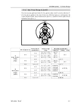
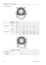
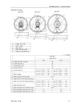
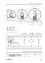
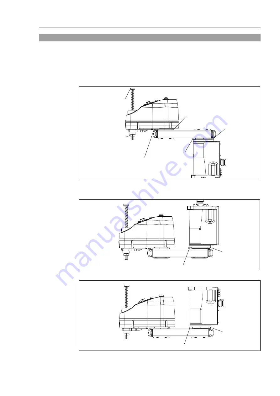
5.2 Motion Range Setting by Mechanical Stops
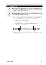
Mechanical stops physically limit the absolute area that the Manipulator can move.
Both Joints #1 and #2 have threaded holes in the positions corresponding to the angle for
the mechanical stop settings. Install the bolts in the holes corresponding to the angle that
you want to set.
Joints #3 can be set to any length less than the maximum stroke.
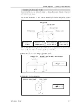
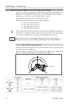
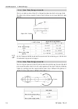
Table top mounting
Joint #3 mechanical stop
(lower limit
mechanical stop)
Joint #3 mechanical stop
(upper limit
mechanical stop) *
Joint #2 mechanical stop
(variable)
Joint #2 mechanical stop
(stable)
Joint #1
mechanical stop
(stable)
Joint #1
mechanical stop
(variable)
* Do not move the position of upper limit mechanical stop.
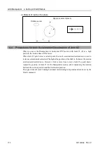
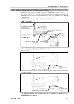
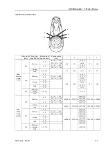
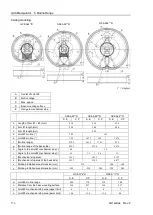
Wall mounting
Joint #1 mechanical stop (stable)
Joint #1
mechanical stop
(variable)
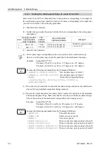
Ceiling mounting
Joint #1 mechanical stop (stable)
Joint #1
mechanical stop
(variable)
The different mechanical stop positions from Table top mounting are indicated for Wall
mounting and Ceiling mounting.
Summary of Contents for SCARA GX Series
Page 1: ...Original instructions Rev 2 EM221R5129F SCARA Robots GX series Manual ...
Page 2: ...GX series Manual Rev 2 ...
Page 12: ......
Page 86: ...GX4 Manipulator 5 Motion Range 76 GX series Rev 2 ...
Page 88: ......
Page 188: ......
Page 202: ......


