GX4 Manipulator 2. Specifications
24
GX series Rev.2
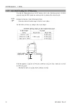
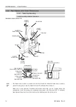
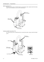
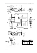
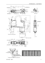
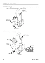
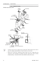
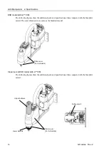
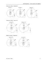
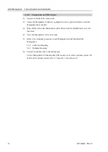
2.2.2 Multiple Mounting
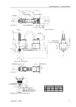
Standard-model GX4-A**1SM
Joint #3
(up and down)
Joint #2
(rotating)
Joint #1
(rotating)
Joint #4
(rotating)
Arm #2
Arm #1
Joint #3 #4
brake release switch
Base
Shaft
Face plate
(Manipulator serial No.)
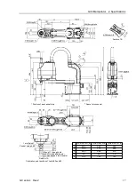
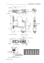
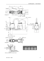
Ethernet
connector
M/C cable
connector
User connector
(15-pin D-sub connector)
Fitting (white)
for ø6 mm
pneumatic tube
Indicating lamp
Fitting (blue)
for ø4 mm pneumatic tube
Fitting (blue)
for ø6 mm
pneumatic tube
+
−
+
−
+
−
+
−
Conduit tube
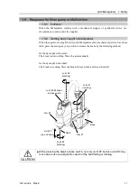
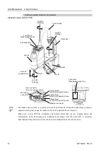
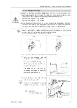
- The brake release switch is common to Joint #3 and Joint #4. When the brake release switch is
pressed in emergency mode, the brakes for Joint #3 and Joint #4 are released.
- Make sure to turn OFF the Controller and inform others that you are working before the
maintenance work. Performing any replacement procedure with the power ON is extremely
hazardous and may result in electric shock and/or malfunction of the robot system.
NOTE
Summary of Contents for SCARA GX Series
Page 1: ...Original instructions Rev 2 EM221R5129F SCARA Robots GX series Manual ...
Page 2: ...GX series Manual Rev 2 ...
Page 12: ......
Page 86: ...GX4 Manipulator 5 Motion Range 76 GX series Rev 2 ...
Page 88: ......
Page 188: ......
Page 202: ......


