background image

5 Application example

5.7 Example program – DX-NET-PROFINET2-2 with TIA Portal

DX-NET-PROFINET2-2

01/22 MN040062EN

www.eaton.com

109

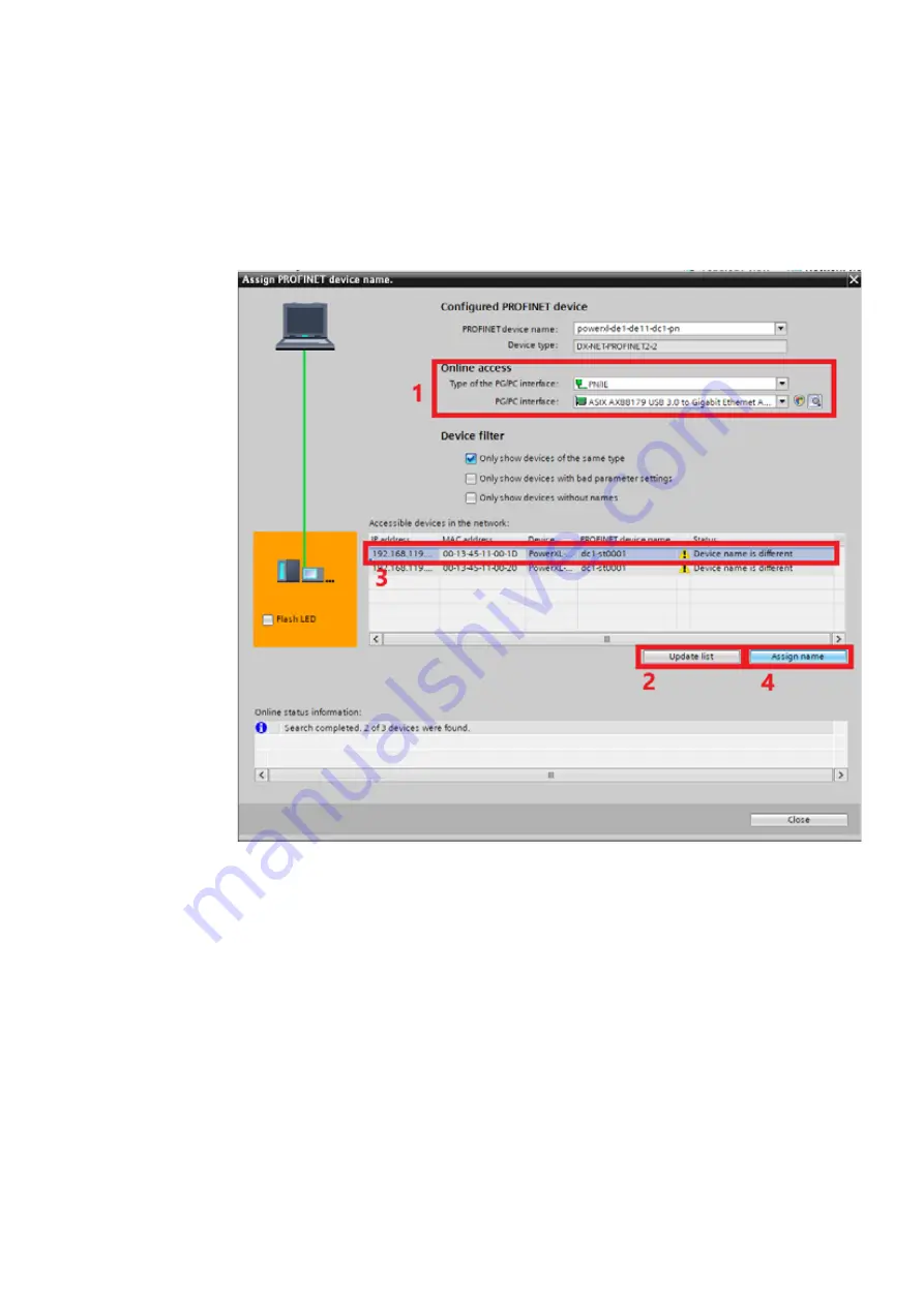
10.Select the properties of the DX-NET-PROFINET2-2 communication 

interface.

You can assign the IP address and the device name in the “PROFINET inter-
face” settings. Then click 

Assign name

.

Figure 48:

Assigning device names

Summary of Contents for DX-NET-PROFINET2-2

Page 1: ...Manual DX NET PROFINET2 2 PROFINET communication interface for PowerXL DE1 variable speed starters and DC1 variable frequency drives 01 22 MN040062EN...

Page 2: ...Resource Center Voice 877 ETN CARE 386 2273 option 2 option 6 8 00 a m 5 00 p m Central Time U S UTC 6 email TRCDrives Eaton com www eaton com drives Original operating manual The German language edit...

Page 3: ...mation system may cause damage to persons or property external measures must be implemented to ensure a safe operating state in the event of a fault or malfunction for example by means of separate lim...

Page 4: ...ted operational data 8 1 4 Pin assignment 9 1 4 1 PROFINET connection 9 1 4 2 Serial interface 10 1 4 3 External 24 V DC control voltage 11 1 5 Proper use 12 1 6 Maintenance and inspection 13 1 7 Stor...

Page 5: ...4 11 1 Control words 56 4 11 2 Status words 58 4 12 Acyclic data 60 4 12 1 Introduction 60 4 12 2 Data types 60 4 12 3 Parameter list 63 4 12 4 Further explanations 83 4 12 5 Errors and diagnostics 9...

Page 6: ...r are also described 0 2 Target audience This manual MN040062EN is intended for engineers electricians and automation technicians A thorough knowledge of the ProfiNet communication system and the prog...

Page 7: ...death or serious injury DANGER Indicates an imminently hazardous situation that will result in death or serious injury Indicates useful tips The housing as well as other safety relevant parts has bee...

Page 8: ...le frequency drives MN040028EN Manual DC1 S variable frequency drive MN040011EN Manual DE1 variable speed starter Variable Speed Starter VSS DXE EXT SET configuration module IL04020009Z Instruction le...

Page 9: ...conversion examples dec decimal number system based on 10 EMC Electromagnetic compatibility FB Field bus FS Frame size GND Ground 0 V potential GSD Generic Station Description electronic data sheet H...

Page 10: ...using a suitable means of transportation Please take note of the labels and instructions on the packaging as well as the manual for the unpacked device Open the packaging with suitable tools and insp...

Page 11: ...The variable frequency drive variable speed starter complies with the EMC standard EN 61800 3 20218 Installation In RJ45 slot on the drive Degree of protection IP20 Connections RJ45 plug for variable...

Page 12: ...DX NET PROFINET2 2 communication interface Generally connection cables with RJ45 plugs for PROFINET are available as standard ready for use cables They can also be prepared individually This will req...

Page 13: ...s a connection to the RJ45 socket This is located on the front of the DX NET PROFINET2 2 communication interface Figure 5 RJ45 interface Figure 6 Pin assignment for RJ45 plugs PIN Meaning 1 2 3 0 V 4...

Page 14: ...er supply Figure 7 External power supply You can establish communication with the PLC assign the IP address and ProfiNet network name The external control voltage 24 V DC must be able to handle a load...

Page 15: ...FINET2 2 communication interface is not a device for household use and is designed exclusively for use in commercial applica tions Observe the technical data and connection requirements described in t...

Page 16: ...nents s lifespan and function We therefore recommend that you check the device regularly If the DX NET PROFINET2 2 communication interface is damaged by external influences repair is not possible Indi...

Page 17: ...has occurred with the DX NET PROFINET2 2 device Information concerning the warranty can be found in the Eaton Industries GmbH Terms and Conditions For service and support please contact your local sal...

Page 18: ...ication connections Take the effect of unforeseen transmission delays and connec tion problems into account Carefully and individually test every implementation of a product before putting it into ope...

Page 19: ...riable speed starters Firmware The DX NET PROFINET2 2 communication interface can be used with firmware in the following cases Basic device DC1 DE1 Firmware version from V 2 04 from V 2 11 The firmwar...

Page 20: ...ents c MS LED LED to indicate module status d NS LED LED to indicate network status e COMM LED LED to indicate the communication status to the basic unit DC1 DE1 f ERROR LED LED to indicate faults or...

Page 21: ...ction to the IO controller available Green flashing Online but no communication present Green illuminating The connection to the PROFINET network has been established however there is a communication...

Page 22: ...asic unit LED status Description Off green Port not connected Green flashing Data transfer in progress and communication active Illuminated yellow An Ethernet connection has been established and a dat...

Page 23: ...2 Configuration 2 2 LEDs 20 DX NET PROFINET2 2 01 22 MN040062EN www eaton com...

Page 24: ...information when setting up the system Figure 10 Only carry out installation work in a voltage free state Perform all installation work only with the indicated appropriate tools and do not apply any f...

Page 25: ...C1 variable frequency drive or DE1 variable speed starter In order to do this with a variable frequency drive or variable speed starter the two cover plugs must first be removed with a flat blade scre...

Page 26: ...INET2 2 communication interface can be mounted on all DC1 variable frequency drives with degree of protection IP20 as well as on all DE1 variable speed starters The DX NET PROFINET2 2 communication in...

Page 27: ...field bus cables and energy carrying mains and motor cables must be greater than 30 cm Cables should always intersect at right angles Figure 13 Routing cables for PROFINET and mains motor cables If t...

Page 28: ...missioning the variable frequency drive or variable speed starter as described in the relevant manual for the device Check the settings and installations for the switching on the PROFINET communicatio...

Page 29: ...nizes the I O device in the network via its name The following instructions explain how to configure the IP address for the DX NET PROFINET2 2 communication interface Connect the communication interfa...

Page 30: ...network adapter from the drop down menu of the network interface Figure 16 Select the network adapter The program then displays all available communication interfaces Figure 17 View of the available c...

Page 31: ...2 2 01 22 MN040062EN www eaton com Click on Apply Figure 18 Setting the IP address You will then see the assigned IP address under IP Figure 19 The DX NET PROFINET2 2 communication interface now has a...

Page 32: ...work If parameter P 12 is set to 9 the system can only be operated via the network The system is controlled and referenced only via the network It is not possible to switch to another control level 2...

Page 33: ...l ENA Enable A start signal START FWD REV is additionally required for starting If ENA is removed the drive will coast EXTFLT External fault FWD Used to start the drive in the forward direction FWD Fo...

Page 34: ...erminal 3 DI3 AI2 Terminal 4 DI4 AI1 Terminal 6 0 ENA No function No function No function 1 ENA No function No function No function 2 ENA No function No function No function 3 ENA Select BUS REF f Fix...

Page 35: ...gnal must always be present at DI1 DE1 For PROFINET operation a high signal must always be present at DI1 DANGER Commissioning must only be carried out by qualified technici ans DANGER DANGEROUS ELECT...

Page 36: ...munication specific parameters such as ModbusRTU are locked Changing the parameter values via drivesConnect or the control unit requires a connection to the RJ45 socket This is located on the front of...

Page 37: ...c data Parallel communication via PROFINET keypad DX COM STICK3 or a PC cable connection is always possible A real time processing mode via drivesConnect is not however recommen ded as this would over...

Page 38: ...ed by the PROFIBUS Nutzerorganisation e V PNO for cyclic data exchange with a drive Control and status data will be processed as per the PROFIdrive profile The Standard Telegram 1 communication profil...

Page 39: ...to the PROFIdrive profile 4 2 The grey boxes in the figures represent the current state S State with the help of the input bytes The white boxes represent the transition conditions with the help of t...

Page 40: ...diagram PROFIdrive S1 Switching On Inhibited Bit 6 1 Bit 0 1 2 0 S2 Ready For Switching On Bit 0 1 Bit 1 2 6 0 S3 Switched On Bit 0 1 1 Bit 2 6 0 S4 Operation Bit 0 1 2 1 Bit 6 0 Standstill or Bit 3...

Page 41: ...ive S1 Switching On Inhibited Bit 6 1 Bit 0 1 2 0 S2 Ready For Switching On Bit 0 1 Bit 1 2 6 0 S3 Switched On Bit 0 1 1 Bit 2 6 0 S4 Operation Bit 0 1 2 1 Bit 6 0 Standstill or Bit 3 0 EN_Op Standsti...

Page 42: ...Profile name Data length Standard Telegram 1 ProfiDrive 2 x 16 bit Vendor specific 1000 PDShort 8 bit 2 x 16 bit Vendor specific 999 Transparent Mode 2 x 16 bit NOTES ON NAMING CONVENTION USED THROUG...

Page 43: ...Profile name data length Input word control of PLC variable frequency drive variable speed starter Vendor specific 1000 PDShort 8 bit 2 x 16 bit Control word 1 VFD control Control word 2 VFD frequenc...

Page 44: ...le name data length Output word status of variable frequency drive variable speed starter PLC Vendor specific 1000 PDShort 8 bit 2 x 16 bits Status word 1 VFD status Status word 2 VFD frequency actual...

Page 45: ...r the PDShort profile Table 8 Control words for the PDShort profile The individual parts of the words are explained below Telegram Profile name data length Input word control of PLC variable frequency...

Page 46: ...to reset a fault in the variable frequency drive variable speed starter The fault acknowledge function will only respond to a rising edge i e to the value changing from 0 to 1 4 f Source Setpoint sou...

Page 47: ...output of the variable frequency drive variable speed starter is activated Bits 8 to 15 are not used Byte Bit Designation Meaning 1 0 7 High Setpoint Setpoint as a percentage The setpoint is specified...

Page 48: ...frequency drive variable speed starter is active 2 RDY Ready switched on 0 Not switched on mains voltage is missing or there is an error 1 Switched on and no error present Indicates whether the varia...

Page 49: ...ile Byte Bit Designation Meaning 1 0 7 High ActSpeed Frequency actual value current speed in percent 100 4000hex 0 0x0000hex Examples 1 f min P 02 0 Hz 0dec 0x0000hex 0 2 f max P 01 50 Hz 16384dec 0x4...

Page 50: ...words are available for the PROFIdrive profile Table 15 Control words for the PROFIdrive profile The individual parts of the words are explained below Telegram Profile name data length Input word cont...

Page 51: ...le speed starter moves up with the set ramp 5 Unfreeze Unfreeze ramp 0 Freeze ramp the ramp generator s current output value will be frozen 1 Unfreeze ramp With a value of 0 the variable frequency dri...

Page 52: ...riable frequency drive variable speed starter Until then no commands that the variable frequency drive variable speed starter receives from the PLC are accepted 3 f Source Setpoint source The source f...

Page 53: ...negative setpoint Example 100 C000hex Byte Bit Designation Meaning 0 0 7 High Setpoint Setpoint as a percentage The frequency setpoint is specified as an integer value between 100 and 100 100 4000hex...

Page 54: ...the PROFIdrive profile Table 19 Status words for the PROFIdrive profile The individual parts of the words are explained below Telegram Profile name data length Output word status of variable frequency...

Page 55: ...1 the variable frequency drive s variable speed starter s power section IGBTs is active 3 ERR Error present 0 no error 1 Fault Indicates whether there is a variable frequency drive variable speed star...

Page 56: ...lue signalling threshold 0 Actual speed is less than or equal to the signaling threshold 1 Actual speed is greater than the signalling threshold As soon as the actual speed is greater than the value s...

Page 57: ...f a setpoint has been specified Value Description 16 047F The variable frequency drive variable speed starter is in operation 16 046F The variable frequency drive variable speed starter executes the r...

Page 58: ...eeds to be reset Fault Ack The step sequence must then be repeated starting from there Setpoints via input bytes 2 and 3 are displayed as integer values 100 4000hex The direction of rotation is specif...

Page 59: ...nsparent Mode profile Control word 1 These bits are used to control the variable frequency drive variable speed starter The content can be adapted to your application and then sent as a control word t...

Page 60: ...FF1 7 No action Overwrite setpoint value with 0 Bits 8 to 15 are not used CAUTION When bit 0 and bit 1 are activated in input byte 0 the output of the variable frequency drive variable speed starter...

Page 61: ...le name data length Output word status of variable frequency drive variable speed starter PLC Vendor specific 999 Transparent Mode 4 x 16 bits Status word 1 FU status and actual errors Status word 2 V...

Page 62: ...ual speed of the variable frequency drive variable speed starter ranges between P 02 minimum frequency and P 01 maximum frequency In the application the values will be scaled by a factor of 0 1 1 Byte...

Page 63: ...types Several data types are defined for using PROFIdrive communication PROFI drive specific data types as well as standard data types PROFIdrive specific data types TimeDifference The value used for...

Page 64: ...Positive numbers including 0 SN 1 Negative numbers Table 38 Octet structure Bit sequence V2 In this bit string 16 variables of type BOOLEAN are represented in two octets Code 115dec 73hex Table 39 Bi...

Page 65: ...constant sampling time Ta Ta is the smallest sampling time defined in PNU 962 It is required here to calculate T2 The following applies T2 i x Ta Table 41 Time constant T2 Standard data types Table 42...

Page 66: ...but does not have a parameter number A minus sign means that the parameter is not available on the device Abbreviation Meaning PNU Parameter number parameter designation used by the drivesConnect para...

Page 67: ...xed frequency 4 4000hex 100 100 20 1 5 RUN rw N2 f Fix5 4000hex 100 100 20 1 6 RUN rw N2 f Fix6 4000hex 100 100 20 1 7 RUN rw N2 f Fix7 4000hex 100 100 20 1 8 RUN rw N2 f Fix8 4000hex 100 100 20 1 20...

Page 68: ...from a latching to the rated motor frequency set in P 09 300 3 00 s 3 RUN rw t accNetwork Ramp time via field bus 114 0 P 04 P 04 RUN rw T2 t dec Sets the deceleration ramp time in seconds The time se...

Page 69: ...al place Example 14 1 4 A 211 0 P 07 P 07 STOP rw U16 Motor rated voltage Used to define the motor s rated operating voltage e g the voltage on the motor when it is running at the rated frequency Deta...

Page 70: ...r analog input value range between 0 and 7 For more information please refer to the manual for the basic device 1 P 47 RUN rw U16 AI2 signal range Signal range for analog input value range between 0 a...

Page 71: ...ime for the variable frequency drive s variable speed starter s maintenance interval 2 RUN rw U16 Auto Reset Delay Wait time between a fault and an auto reset 380 0 RUN rw U16 DisplayScale source Scal...

Page 72: ...source for terminal control mode For more information please refer to the manual for the basic device 4 RUN rw digRef UP Source Control source Up pushbutton For more information please refer to the ma...

Page 73: ...30 0 STOP rw SpeedSource1 1 STOP rw SpeedSource2 2 STOP rw SpeedSource3 3 STOP rw SpeedSource4 4 STOP rw SpeedSource5 5 STOP rw SpeedSource6 6 STOP rw SpeedSource7 7 STOP rw SpeedSource8 431 0 STOP rw...

Page 74: ...ation on the available settings please refer to the manual for the basic device 454 0 P 54 P 53 DE11 RUN rw U16 RO1 HysteresisWidth Relay hysteresis band 457 0 P 55 P 54 460 0 P 25 RUN rw U16 AO1 Func...

Page 75: ...alog input1 Level of the signal applied to analog input 1 after scaling and offsets have been applied 1 P0 02 STOP ro U16 Analog input2 500 50 0 570 0 STOP ro Analog output1 500 50 0 1 STOP ro Analog...

Page 76: ...d to define the drive s behavior when it is started and controlled using the keypad P 12 P1 12 1 or 2 or when it is controlled using the UP and DOWN signals on the terminals 624 0 P 32 RUN rw WORD Aut...

Page 77: ...Over Voltage instead of automatically increasing the motor ramp times 627 0 RUN rw Fan control 630 0 RUN rw FieldbusRampControl Ramp via field bus 0 disabled 1 activated 1 RUN rw WORD Ramp Mode Ramp s...

Page 78: ...12 STOP ro U32 t Run since Trip The drive s operating time since the most recent fault in hours minutes and seconds 6 P00 24 STOP ro U16 t Run PCB in OT The drive s operating hours at a temperature h...

Page 79: ...P00 37 STOP ro FaultCounter braking chopper overcurrent The number of braking chopper overcurrent faults since its date of manufacture 29952 P00 39 STOP ro FaultCounter Communica tion Loss Number of M...

Page 80: ...le7 Log 855 0 P00 17 P00 17 STOP ro U16 MotorCurrent0 Log Displays the most recent 8 samples of the Motor current prior to a drive trip condition occurring The sample interval is 250 ms 100 10 0 A 1 P...

Page 81: ...to 10 ms Basis for all T parameters 964 0 STOP ro UInt16 PDP manufacturer 1 STOP ro UInt16 PDP device type 2 STOP ro UInt16 PDP FW interface 3 STOP ro UInt16 PDP FW year 4 STOP ro UInt16 PDP FW DayMo...

Page 82: ...utput limit 2121 0 RUN rw U16 PID1 Output upper Limit Upper PID output limit 2122 0 RUN rw U16 PID1 OutCalc Used to select the PID output limit 2123 0 P 43 RUN rw WORD PID1 Mode Operation Mode 0 direc...

Page 83: ...0 0 RUN rw U16 Brake release delay Motor brake release time 1 RUN rw U16 Brake Apply Delay Motor brake engagement delay 2251 0 RUN rw U16 Brake M Level Release Minimum torque for releasing the brake 2...

Page 84: ...N rw User M setpoint 2503 0 RUN rw User t acc 1 RUN rw User t accModbus 2504 0 RUN rw User DisplayScaling 2510 0 RUN rw U16 SlaveSpeedScalingCon trol Used to select speed scaling 2511 0 RUN rw S16 Sla...

Page 85: ...ime between the moment communications are lost and the moment the device is swit ched off as a result 3302 0 P 50 RUN rw U16 CAN0 Baudrate CANopen Baudrate For more information please refer to the man...

Page 86: ...e the parameters 927 and 928 1 The parameters can be changed via PROFINET and not directly on the variable frequency drive variable speed starter An exception here are the parameters 927 and 928 PNU 9...

Page 87: ...set and waits for a reset command to reset the error bit a restart is not required The variable frequency drive variable speed starter runs to the end or communication returns with valid commands PNU...

Page 88: ...will not be carried out In the event of an internal error in the variable frequency drive variable speed starter the normal error reaction is executed In the error free state communication takes place...

Page 89: ...request will define whether the job is a read job or a write job After the write request is transmitted contains read or write job a write res ponse without data will be expected Then prompted by the...

Page 90: ...he master can increment the identification number for each new request in the application They are then mirrored by variable frequency drive variable speed starter 01hex FFhex i e 1dec 255dec 1 Reques...

Page 91: ...in the application They are then mirrored by variable frequency drive variable speed starter 01hex FFhex i e 1dec 255dec 1 Request ID Request ID Specifies the type of request 02hex Write job 2 DO ID...

Page 92: ...e speed starter will respond to a received write request with a write response The following write responses are possible Write response without data and errors if the write request was under stood by...

Page 93: ...channel error If the error concerns the PROFIdrive parameter channel Read response without data if the variable frequency variable speed starter drive has determined the reply during a write order Rea...

Page 94: ...dex 03 Bad subindex Attempting to access to a non available subindex in a string or array parameter Subindex 04 Not an array Attempting to use a subindex in order to access a parameter without index 0...

Page 95: ...ot permissible Write request Invalid format or format not permissible for this para meter 0 18 No of values are not consistent Write request The number of values in the parameter data does not match t...

Page 96: ...with data Byte Designation Description 0 Request Reference Request identification Is mirrored 1 Response ID Response ID 02hex Write job 2 DO ID Drive object ID Is mirrored 3 No of Parameters Number of...

Page 97: ...data Table 52 Read response with data Byte Designation Description 0 Request Reference Request identification Is mirrored 1 Response ID Response ID 01hex Read job 2 DO ID Drive object ID Is mirrored...

Page 98: ...AG A device response if any will be described in the advanced diagnostics In addition in all profiles the bits ERR the variable frequency drive stops or WARN no response by the variable frequency driv...

Page 99: ...N bits indicate whether diagnostic messages i e errors or warnings are present Error acknowledgment You can acknowledge faults ERR as follows FaultAck 1 Warnings WARN cannot be acknowledged since they...

Page 100: ...Link voltage ripple 14 0U DC1 DE1 P LOss Incoming power phase failure only for devices with a three phase power supply 15 0F DE1 h O I Overcurrent at output DC1 motor pick up control fault 16 0A DC1...

Page 101: ...4 Commissioning 4 12 Acyclic data 98 DX NET PROFINET2 2 01 22 MN040062EN www eaton com...

Page 102: ...rive specialists and automation technicians Basic knowledge of the PROFINET communication system and the programming of a PROFINET controller is required In addition knowledge of handling the drive is...

Page 103: ...ommunication network Figure 37 Integration of DX NET PROFINET2 2 into a PROFINET network a PC with engineering tool b I O controller c Switch d DC1 variable frequency drive and DE1 variable speed star...

Page 104: ...FB286 function block 5 4 Configuration of the IP address peripheral addresses and device names The TIA Portal software automatically assigns addresses and names for proper communication These can be c...

Page 105: ...ds the status word and the actual value frequency back to the PLC Control and status data are thereby processed as per the PROFIdrive profile The following data exchange takes place in this example In...

Page 106: ...ter PLC and the DX NET PROFINET2 2 communication interface slave certain hardware and software components are assumed to be present In this example the following components are used Configuration PC w...

Page 107: ...ww eaton com 5 7 3 Setting up the configuration in the TIA Portal The steps below describe how to create a project for cyclic and acyclic communication Hardware configuration 1 Start the TIA Portal an...

Page 108: ...NET2 2 with TIA Portal DX NET PROFINET2 2 01 22 MN040062EN www eaton com 105 3 Find a suitable CPU Figure 40 Integrating a CPU 4 Locate a device description file GSDML file for the DX NET PROFINET2 2...

Page 109: ...ng the GSDML file 6 Drag and drop the DX NET PROFINET2 2 into the network Catalog Other PROFINET IO field devices Drives EATON Industries DX NET PROFINET2 2 Figure 43 Integrating the DX NET PROFINET2...

Page 110: ...0062EN www eaton com 107 Figure 44 Entering the IP address for the CPU Now for the DX NET ETHERNET2 2 device Open Properties Select Ethernet addresses Insert a new subnet Enter the desired IP address...

Page 111: ...this connect the Ethernet ports of the controller and the commu nication interface to one another Figure 46 Connecting the ports 9 Assign a device name to the DX NET PROFINET2 2 communication interfa...

Page 112: ...al DX NET PROFINET2 2 01 22 MN040062EN www eaton com 109 10 Select the properties of the DX NET PROFINET2 2 communication interface You can assign the IP address and the device name in the PROFINET in...

Page 113: ...MN040062EN www eaton com 11 Select the required telegram from the hardware catalog In this example Standard Telegram 1 is used Figure 49 Selecting a telegram Hardware and I O address overview The ass...

Page 114: ...e help of the Siemens SINA_SPEED block the variable frequency drive can be controlled cyclically with the Standard Telegram 1 The SINA_SPEED function block must be created and then called in OB1 The S...

Page 115: ...Sp REAL 0 0 rpm Speed reference RefSpeed 0 0 rpm Rated speed of the drive p2000 ConfigAxis WORD 3 ConfigAxis input HWIDSTW HW_IO 0 Symbolic name or HW ID on the SIMATIC S7 1200 1500 of the setpoint sl...

Page 116: ...eters of the SINA_SPEED function block The HWIDSTW and HWIDZSW block inputs must reference the hardware ID of Standard Telegram 1 Telegram slots Figure 52 Definition of the slots When using a PROFINET...

Page 117: ...n com Specific information about the data block The inputs of Standard Telegram 1 can be accessed via the InstSinaSpeed data block The InstSinaSpeed data block contains the following information Input...

Page 118: ...062EN www eaton com 115 Configuration of the block 1 Open the SINA_SPEED block from the Drive_Lib library Figure 54 Selecting the SINA_SPEED block from the Drive_Lib library 2 Insert the SINA_SPEED bl...

Page 119: ...th TIA Portal 116 DX NET PROFINET2 2 01 22 MN040062EN www eaton com 3 Call the SINA_SPEED block in the Main OB OB1 Assign a data block to the block Figure 56 Call options 4 Declare inputs and outputs...

Page 120: ...ogram DX NET PROFINET2 2 with TIA Portal DX NET PROFINET2 2 01 22 MN040062EN www eaton com 117 Figure 58 Network 1 Saving the project 5 Save the project and download it to the CPU To do this click Con...

Page 121: ...om Control and monitoring In order to be able to control the variable frequency drive via the TIA Portal the variables must be called in the monitoring table Figure 60 Settings in the monitoring table...

Page 122: ...nication is established according to the PROFIdrive profile via data block 47 The FB286 acyclic communication block SINA_PARA provides the user with an interface for easy reading and writing of any 16...

Page 123: ...TIA Portal 120 DX NET PROFINET2 2 01 22 MN040062EN www eaton com 2 Assign a name for the block Figure 62 Assigning a name for the block 3 Drag and drop function block FB286 into the network Figure 63...

Page 124: ...2 2 01 22 MN040062EN www eaton com 121 The following figure shows the FB286 function block with variables Figure 64 Function block FB286 The following figure shows the entry for the DX NET PROFINET2 2...

Page 125: ...e program DX NET PROFINET2 2 with TIA Portal 122 DX NET PROFINET2 2 01 22 MN040062EN www eaton com Loading a project 4 Select the appropriate controller in the project tree Figure 66 Selecting the con...

Page 126: ...Reading writing parameters in online mode Now you switch to online mode to record and write the parameter values Read Figure 67 Monitoring table for read parameters You can find a description of the...

Page 127: ...ad Set the following values for the variables of the instance database of function block FB286 Frequency reference SINA_PARA_DB sxParameter 1 siParaNo 1 index number SINA_PARA_DB sxParameter 1 siIndex...

Page 128: ...function block FB286 SINA_PARA_DB sxParameter 1 siParaNo 20 index number SINA_PARA_DB sxParameter 1 siIndex 1 subindex SINA_PARA_DB sxParameter 1 srValue 700 parameter is changed to 70 Hz P1 01 f min...

Page 129: ...ET2 2 01 22 MN040062EN www eaton com Changed parameter values The changed parameter values are shown below Figure 69 Changed parameter values To change an individual parameter the parameter value is w...

Page 130: ...he value of the corresponding job field to be read is then stored in the structure Parameter Type Default setting Description Start BOOL 0 Start of the job 0 No job or cancel job 1 Start and execute t...

Page 131: ...siParaNo parameter number sxParameter x1 siIndex parameter index sxParameter x srValue value range 1 175 495 x 10 38 to 3 402823 x 1038 is filled when the block is read sxParameter x sdValue value ran...

Page 132: ...19 F Firmware 16 I Inspection 13 M Maintenance 13 MS LED 18 N NS LED 18 P Power supply external 11 R Rated operational data 8 Repair 13 Residual ripple 11 RJ45 jack 9 S Safety warning concerning perso...

Page 133: ...l power management across industries experts at Eaton deliver customized integrated solutions to solve our customers most critical challenges Our focus is on delivering the right solution for the appl...

Reviews: