


Chapter 10 Digital Keypad
CP2000
10-27
4.
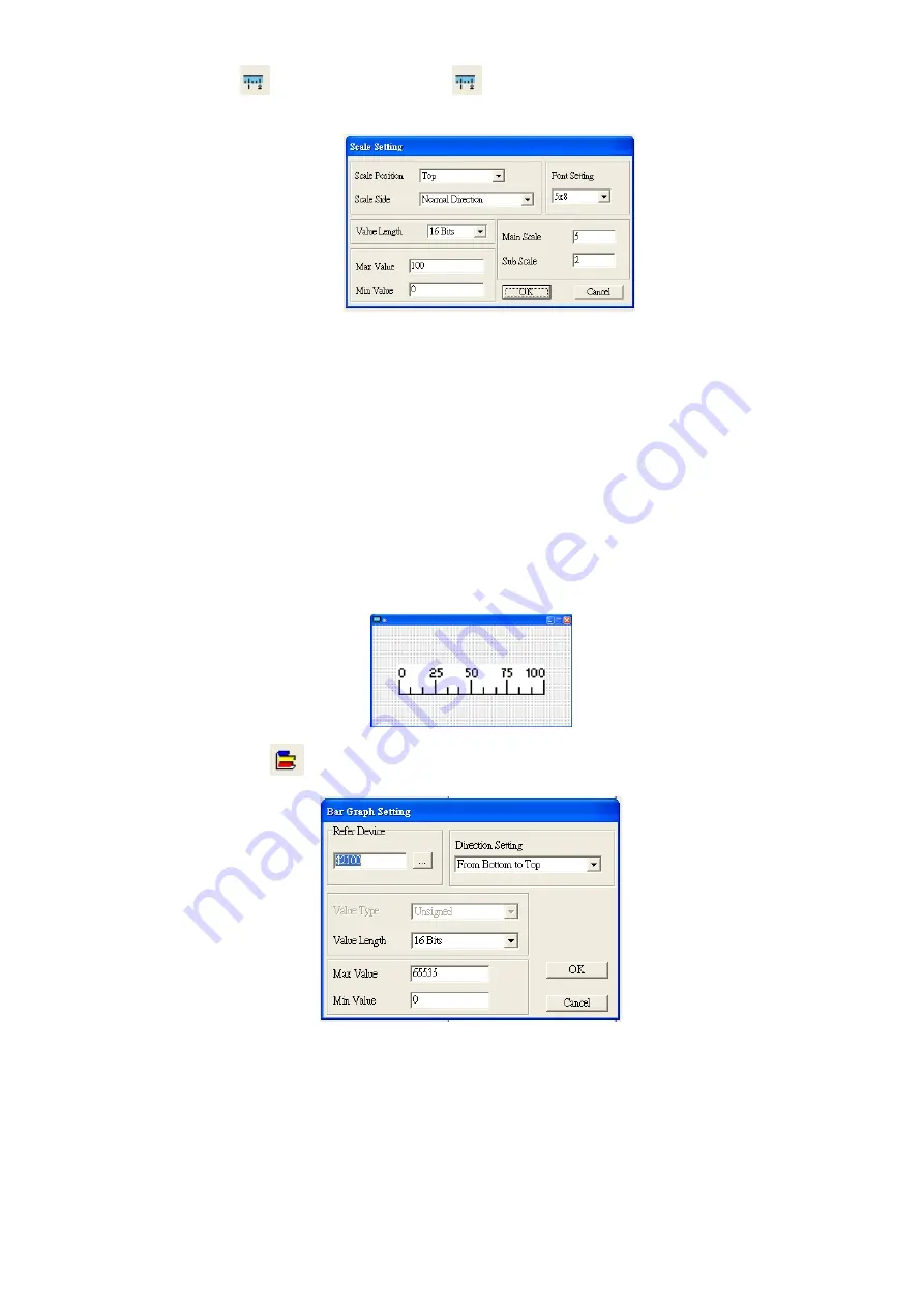
Scale Setting
: On the Tool Bar, click on
for Scale Setting. You can also edit Scale Setting in the
Property Window on the right hand side of your computer screen.
a.
Scale Position: Click on the drop down list to choose which position that you need to place a scale.
b.
Scale Side: Click on the drop down list to choose if you want to number your scale from smaller
number to bigger number or from big to small. Click OK to accept this setting or click Cancel to
abort.
c.
Font Setting: Click on the drop down list to choose the Font setting that you need then click OK to
accept the setting or click Cancel to abort.
d.
Value Length: Click on the drop down to choose 16 bits or 32 bits. Then click OK to accept the
setting or click Cancel to abort.
e.
Main Scale & Sub Scale: In order to divide the whole scale into equal parts, key in the numbers of
your choices for main scale and sub scale.
f.
Maximum value & Minimum Value are the numbers on the two ends of a scale. They can be
negative numbers. But the values allowed to be input are limited by the length of value. For
example, when the length of value is set to
be hexadecimal
, the maximum and the minimum value
cannot be input as -4000.
Follow the Scale setting mentioned above; you will have a scale as shown below.
5.
Bar Graph setting
:
a.
Related Device: Choose the VFD Communication Port that you need.
b.
Direction Setting: Click on the drop down menu to choose one of the following directions: From
Bottom to Top, From Top to Bottom, From Left to Right or From Right to Left.
c.
Maximum Value & Minimum Value: They define the range covered by the maximum value and
minimum value. If a value is smaller than or equal to the minimum value, then the bar graph will be
blank. If a value is bigger or equal to the maximum value, then the bar graph will be full. If a value is
between minimum and maximum value, then the bar graph will be filled proportionally.
Summary of Contents for CP2000 Series
Page 3: ......
Page 12: ...Chapter 1 Introduction CP2000 1 3 1 2 Model Name 1 3 Serial Number...
Page 35: ...Chapter 1 Introduction CP2000 1 26 Digital Keypad KPC CC01 Figure 1 32...
Page 42: ...Chapter 3 Unpacking CP2000 3 1 Chapter 3 Unpacking 3 1 Unpacking 3 2 The Lifting Hook...
Page 72: ...Chapter 4 Wiring CP2000 4 1 Chapter 4 Wiring 4 1 System Wiring Diagram 4 2 Wiring...
Page 77: ...Chapter 4 Wiring CP2000 4 6 Figure 4 5...
Page 79: ...Chapter 4 Wiring CP2000 4 8 This page intentionally left bank...
Page 109: ...Chapter 6 Control Terminals CP2000 6 12 This page intentionally left blank...
Page 172: ...Chapter 7 Optional Accessories CP2000 7 63 EMC filter model name EMF018A43A Figure 7 46...
Page 174: ...Chapter 7 Optional Accessories CP2000 7 65 EMC filter model name KMF370A KMF3100A Figure 7 48...
Page 175: ...Chapter 7 Optional Accessories CP2000 7 66 EMC filter model name B84143D0150R127 Figure 7 49...
Page 176: ...Chapter 7 Optional Accessories CP2000 7 67 EMC filter model name B84143D0200R127 Figure 7 50...
Page 182: ...Chapter 7 Optional Accessories CP2000 7 73 Wall Mounting Embedded Mounting...
Page 197: ...Chapter 7 Optional Accessories CP2000 7 88 6 Installation complete...
Page 237: ...Chapter 7 Optional Accessories CP2000 7 128 This page intentionally left blank...
Page 265: ...Chapter 8 Option Cards CP2000 8 28 This page intentionally left blank...
Page 277: ...Chapter 09 Specifications CP2000 9 12 575V 690V Figure 9 3 Altitude Derating Curve Figure 9 4...
Page 281: ...Chapter 09 Specifications CP2000 9 16 9 8 Efficiency Curve Figure 9 11 Figure 9 12...
Page 317: ...Chapter 10 Digital Keypad CP2000 10 36 This page intentionally left blank...
Page 361: ...Chapter 11 Summary of Parameter Settings CP2000 11 44 This page intentionally left blank...
Page 416: ...Chapter 12 Description of Parameter Settings CP2000 12 1 03 3 3 4 5...
Page 417: ...Chapter 12 Description of Parameter Settings CP2000 12 1 03 4 6 7 8...
Page 418: ...Chapter 12 Description of Parameter Settings CP2000 12 1 03 5 9 10 11...
Page 419: ...Chapter 12 Description of Parameter Settings CP2000 12 1 03 6 12 13 14...
Page 420: ...Chapter 12 Description of Parameter Settings CP2000 12 1 03 7 15 16 17...
Page 421: ...Chapter 12 Description of Parameter Settings CP2000 12 1 03 8 18 19 20...
Page 422: ...Chapter 12 Description of Parameter Settings CP2000 12 1 03 9 21 22 23...
Page 423: ...Chapter 12 Description of Parameter Settings CP2000 12 1 03 10 24 25 26...
Page 424: ...Chapter 12 Description of Parameter Settings CP2000 12 1 03 11 27 28 29...
Page 425: ...Chapter 12 Description of Parameter Settings CP2000 12 1 03 12 30 31 32...
Page 426: ...Chapter 12 Description of Parameter Settings CP2000 12 1 03 13 33 34 35...
Page 427: ...Chapter 12 Description of Parameter Settings CP2000 12 1 03 14 36 37 38...
Page 836: ...Chapter 16 PLC Function Applications CP2000 16 153...
Page 838: ...Chapter 16 PLC Function Applications CP2000 16 155...
Page 841: ...Chapter 16 PLC Function Applications CP2000 16 158 This page intentionally left blank...
Page 857: ...Chapter 17 Introduction to BACnet CP2000 17 16 This page intentionally left blank...


