Chapter 19: Hardware Servicing
179
Customer Operations
3.
Remove the power cord.
4.
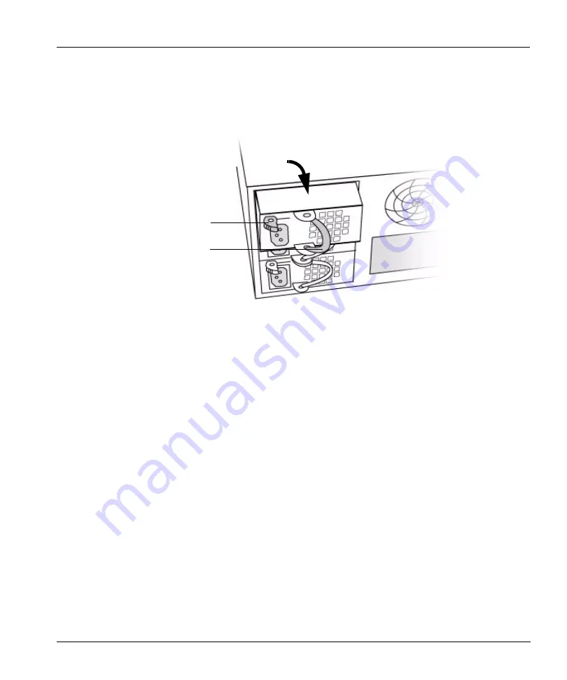
Push the locking lever to the right, pull on the power unit handle, and slide out the unit as
shown in Figure 25.
5.
Slide in the new unit. When the unit is nearly completely in the slot, grasp the handle and push
in the unit with enough force to seat the unit into the frame. Make sure that the unit is seated
securely and that it lines up with the other power units.
6.
Attach the power cord.
7.
Slide the power cord retainer bracket over the cord.
8.
If your system has the power cord retainer brackets, pinch the two “wings” on the bracket and
slide the bracket down over the power cord plug until the bracket is flush with the back of the
power unit. The wings secure the plug by clicking into the power unit handle brackets. See
Figure 26 on page 180.
Locking lever
Handle
Figure 25: Remove a power unit
Summary of Contents for DD400 Series
Page 1: ...Software Version 3 1 2 DD400 Series Restorer User Guide ...
Page 4: ......
Page 38: ...Regulatory Standards Compliance xxxviii DD400 Series Restorer User Guide ...
Page 54: ...Hardware System Level Interfaces 16 DD400 Series Restorer User Guide ...
Page 60: ...Display the Space Usage Graphs 22 DD400 Series Restorer User Guide ...
Page 96: ...The License Command 58 DD400 Series Restorer User Guide ...
Page 102: ...Return Command Output to a Remote machine 64 DD400 Series Restorer User Guide ...
Page 128: ...Clean Operations 90 DD400 Series Restorer User Guide ...
Page 138: ...Display the History of Disk Failures 100 DD400 Series Restorer User Guide ...
Page 182: ...CIFS Command 144 DD400 Series Restorer User Guide ...
Page 194: ...Procedure Replace a Replica 156 DD400 Series Restorer User Guide ...
Page 210: ...Send Log messages to Another System 172 DD400 Series Restorer User Guide ...
Page 228: ...Operations for Trained Service Personnel 190 DD400 Series Restorer User Guide ...


