115
strip, vertical strip, slanting strip and etc.
Noise: The video noise refers to the blurry video, poor video quality. It may result from the optical
system distortion or the hardware problem during the video transmission when recording.
Color cast: Usually the video is color containing RGB. When these three colors displayed in
abnormal rate, we can say color cast occurred.
Out of focus: The clear video presents abundant video details. The video definition decreases when
the distortion event occurs. The out of focus event may result from many sources such as video
transmission, processing and etc.
Overexposure: The color brightness refers to the image pixel intensity. Black is the darkest and the
white is the brightest. We use number 0 to stand for black and use number 255 to stand for white.
Once the brightness threshold of the whole image has exceeded the threshold value, it means the
image is over exposure.
Threshold: The value ranges from 1 to 30. System can generate an alarm once the value is higher
than the threshold you set here.
3.14.2
IVS Plan (Optional)
Important
The IVS plans are for the smart camera. If you do not set a rule here, user may not use the
intelligent functions in Behavior analytics (Chapter 3.14.3), Face detection (Chapter 3.14.4) and
People counting (Chapter 3.14.5) when you are connecting to a smart camera.
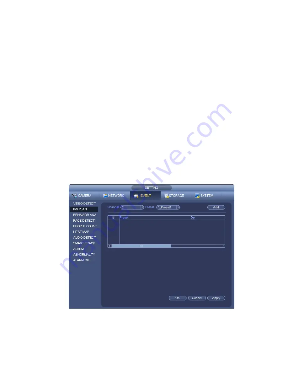
In this interface, user may quickly add an intelligent rule for one preset. The intelligent rule includes
human face detection, behavior analytics and people counting.
From main menu->Setting->Event->IVS plan, the interface is shown as below. See Figure 3-107.
Figure 3-107
Please select a channel number and a preset.
Click Add and then select preset from the dropdown list and then add the intelligent plan. See Figure
3-108.
Summary of Contents for DNA3500 Series
Page 2: ...DNA Network Video Recorder User s Manual V 5 2 0...
Page 123: ...110 Figure 3 98 Figure 3 99 Figure 3 100...
Page 135: ...122 Figure 3 116 Click draw button to draw the zone See Figure 3 117...
Page 139: ...126 Figure 3 120 Click Draw button to draw a zone See Figure 3 121 Figure 3 121...
Page 144: ...131 Figure 3 126 Click draw button to draw the zone See Figure 3 127...
Page 158: ...145 Figure 3 139 Figure 3 140...
Page 159: ...146 Figure 3 141 Figure 3 142...
Page 160: ...147 Figure 3 143 Figure 3 144...
Page 162: ...149 Figure 3 146 Figure 3 147...
Page 187: ...174 Figure 3 173 Figure 3 174...
Page 255: ...242 Figure 4 53 Figure 4 54...
Page 256: ...243 Figure 4 55 Figure 4 56...
Page 279: ...266 Figure 4 90 Figure 4 91...
Page 286: ...273 Figure 4 100 Figure 4 101...


