53
Select the import file and then click OK button.
Note
If the imported IP is already in the added device list, system pops up dialogue box for you to confirm
overwrite or not.
Click OK button, the new IP setup can overwrite the new one.
Click Cancel button, system adds the new IP setup.
Important
User may edit the exported file. Please make sure the file format is the same. Otherwise user may
not import the file again!
System does not support customized protocol import/export.
The import/export function is for the devices of the same language.
3.5.2
Short-Cut Menu
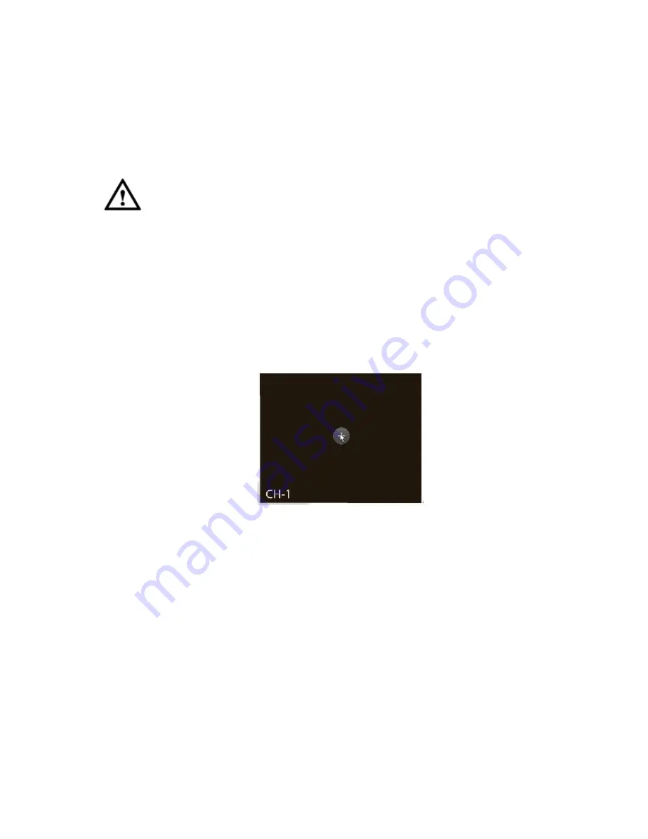
In the preview interface, for the channel of no IPC connection, user may click the icon “+” in the centre of
the interface to quickly go to the Remote Device interface. See Figure 3-26.
Figure 3-26
3.5.3
Image
From main menu->Setting->Camera->Image, user may see the image interface is shown as below.
See Figure 3-27.
Channel: Select a channel from the dropdown list.
Config file: There are three configuration files. System sets proper parameters (such as brightness,
contrastness and etc) for each configuration file. User may select according to your actual situation.
Saturation: It is to adjust monitor window saturation. The value ranges from 0 to 100. The default
value is 50. The larger the number, the strong the color is. This value has no effect on the general
brightness of the whole video. The video color may become too strong if the value is too high. For
the grey part of the video, the distortion may occur if the white balance is not accurate. Please note
the video may not be attractive if the value is too low. The recommended value ranges from 40 to 60.
Brightness: It is to adjust monitor window bright. The value ranges from 0 to 100. The default value is
50. The larger the number is, the bright the video is. When you input the value here, the bright
Summary of Contents for DNA3500 Series
Page 2: ...DNA Network Video Recorder User s Manual V 5 2 0...
Page 123: ...110 Figure 3 98 Figure 3 99 Figure 3 100...
Page 135: ...122 Figure 3 116 Click draw button to draw the zone See Figure 3 117...
Page 139: ...126 Figure 3 120 Click Draw button to draw a zone See Figure 3 121 Figure 3 121...
Page 144: ...131 Figure 3 126 Click draw button to draw the zone See Figure 3 127...
Page 158: ...145 Figure 3 139 Figure 3 140...
Page 159: ...146 Figure 3 141 Figure 3 142...
Page 160: ...147 Figure 3 143 Figure 3 144...
Page 162: ...149 Figure 3 146 Figure 3 147...
Page 187: ...174 Figure 3 173 Figure 3 174...
Page 255: ...242 Figure 4 53 Figure 4 54...
Page 256: ...243 Figure 4 55 Figure 4 56...
Page 279: ...266 Figure 4 90 Figure 4 91...
Page 286: ...273 Figure 4 100 Figure 4 101...


