109
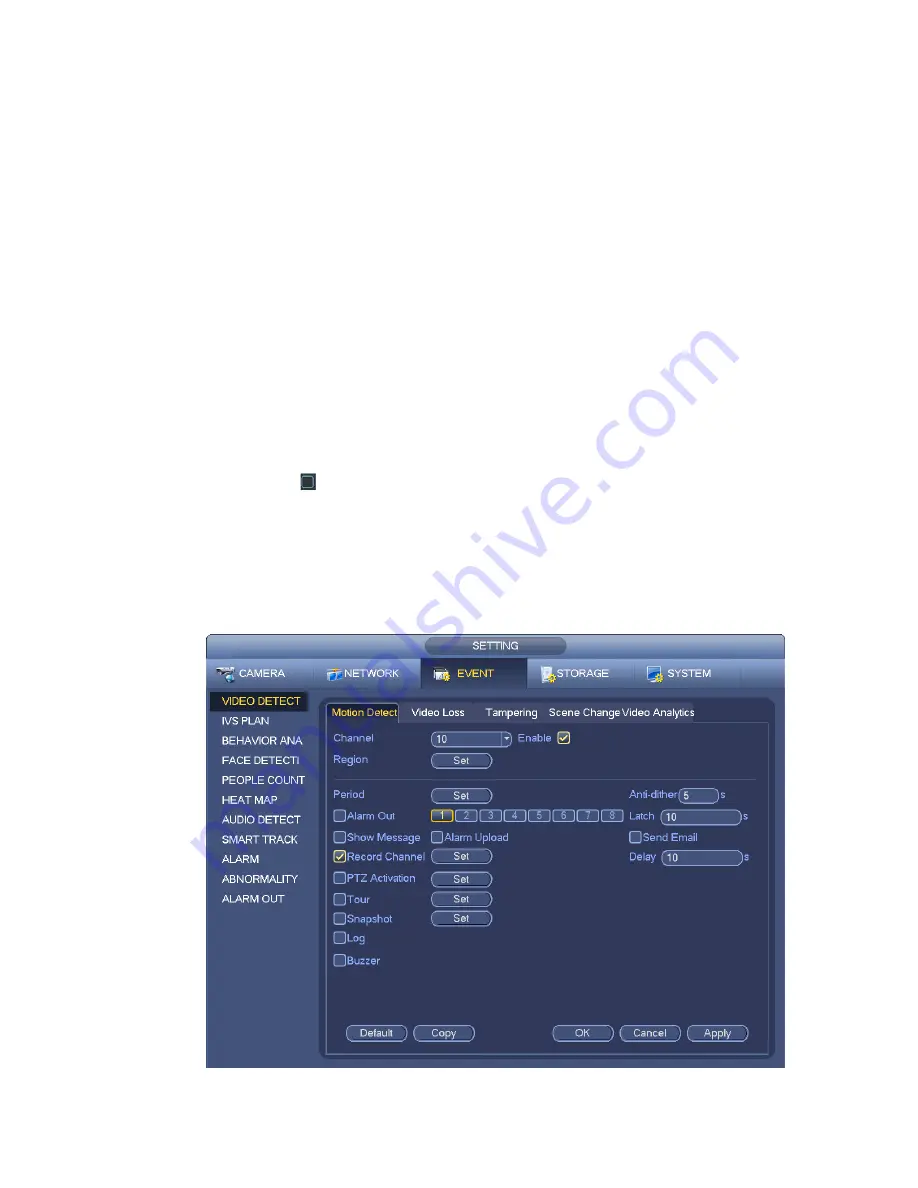
Show message: System can pop up a message to alarm you in the local host screen if you enabled
this function.
Alarm upload: System can upload the alarm signal to the network (including alarm centre) if you
enabled current function.
Send email: System can send out email to alert you when an alarm occurs.
Record channel: System auto activates motion detection channel(s) to record once an alarm occurs.
Please make sure you have set MD record in Schedule interface(Main Menu->Setting->Schedule)
and schedule record in manual record interface(Main Menu->Advanced->Manual Record)
PTZ activation: Here user may set PTZ movement when an alarm occurs. Such as go to preset, tour
&pattern when there is an alarm. Click “select” button, user may see an interface is shown as in
Figure 3-99
X
.
Record Delay: System can delay the record for specified time after alarm ended. The value ranges
from 10s to 300s.
Tour: Here user may enable tour function when an alarm occurs. System one-window tour.
Snapshot: User may enable this function to snapshot image when a motion detect alarm occurs.
Log: Check the box here, system can record motion detect log.
Buzzer: Highlight the icon to enable this function. The buzzer beeps when an alarm occurs.
Please highlight icon
to select the corresponding function. After all the setups please click save
button, system goes back to the previous menu.
Note:
In motion detection mode, user may not use copy/paste to set channel setup since the video in each
channel may not be the same.
In Figure 3-98, user may left click mouse and then drag it to set a region for motion detection. Click Fn to
switch between arm/withdraw motion detection. After setting, click enter button to exit.
Figure 3-97
Summary of Contents for DNA3500 Series
Page 2: ...DNA Network Video Recorder User s Manual V 5 2 0...
Page 123: ...110 Figure 3 98 Figure 3 99 Figure 3 100...
Page 135: ...122 Figure 3 116 Click draw button to draw the zone See Figure 3 117...
Page 139: ...126 Figure 3 120 Click Draw button to draw a zone See Figure 3 121 Figure 3 121...
Page 144: ...131 Figure 3 126 Click draw button to draw the zone See Figure 3 127...
Page 158: ...145 Figure 3 139 Figure 3 140...
Page 159: ...146 Figure 3 141 Figure 3 142...
Page 160: ...147 Figure 3 143 Figure 3 144...
Page 162: ...149 Figure 3 146 Figure 3 147...
Page 187: ...174 Figure 3 173 Figure 3 174...
Page 255: ...242 Figure 4 53 Figure 4 54...
Page 256: ...243 Figure 4 55 Figure 4 56...
Page 279: ...266 Figure 4 90 Figure 4 91...
Page 286: ...273 Figure 4 100 Figure 4 101...


