219
4.8.1.2 Image
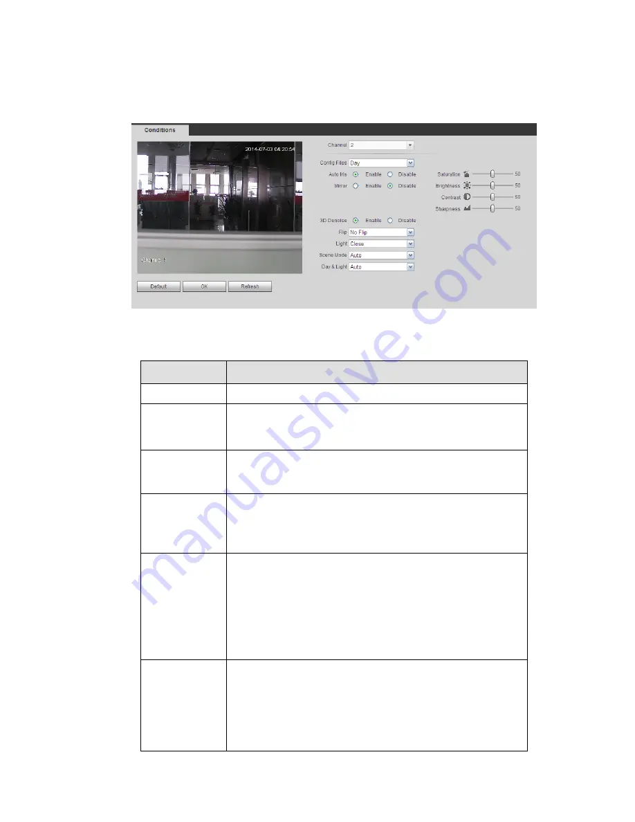
From main window->Setup->Camera->Image, user may see an interface shown as in Figure 4-23.
Here user may view device property information. The setups become valid immediately after you set.
Figure 4-23
Please refer to the following sheet for detailed information.
Parameter
Function
Channel
Please select a channel from the dropdown list.
Config file
The options includes: day/night/general/switch by period. Once
the mode is switch by period, user may set sunset and sunrise
time.
3D NR
It is to process multiple-frame (At least two frames). System
uses the information between these two frames to realize noise
reduction function.
Hue
It is to adjust monitor video brightness and darkness level. The
default value is 50.
The bigger the value is, the large the contrast between the bright
and dark section is and vice versa.
Brightness
It is to adjust monitor window brightness. The default value is 50.
The larger the number is , the bright the video is. When you
input the value here, the bright section and the dark section of
the video will be adjusted accordingly. User may use this
function when the whole video is too dark or too bright. Please
note the video may become hazy if the value is too high. The
value ranges from 0 to 100.The recommended value ranges
from 40 to 60.
Contrast
It is to adjust monitor window contrast. The value ranges from 0
to 100. The default value is 50.
The larger the number is, the higher the contrast is. User may
use this function when the whole video bright is OK but the
contrast is not proper. Please note the video may become hazy
if the value is too low. If this value is too high, the dark section
may lack brightness while the bright section may over
Summary of Contents for DNA3500 Series
Page 2: ...DNA Network Video Recorder User s Manual V 5 2 0...
Page 123: ...110 Figure 3 98 Figure 3 99 Figure 3 100...
Page 135: ...122 Figure 3 116 Click draw button to draw the zone See Figure 3 117...
Page 139: ...126 Figure 3 120 Click Draw button to draw a zone See Figure 3 121 Figure 3 121...
Page 144: ...131 Figure 3 126 Click draw button to draw the zone See Figure 3 127...
Page 158: ...145 Figure 3 139 Figure 3 140...
Page 159: ...146 Figure 3 141 Figure 3 142...
Page 160: ...147 Figure 3 143 Figure 3 144...
Page 162: ...149 Figure 3 146 Figure 3 147...
Page 187: ...174 Figure 3 173 Figure 3 174...
Page 255: ...242 Figure 4 53 Figure 4 54...
Page 256: ...243 Figure 4 55 Figure 4 56...
Page 279: ...266 Figure 4 90 Figure 4 91...
Page 286: ...273 Figure 4 100 Figure 4 101...


