59
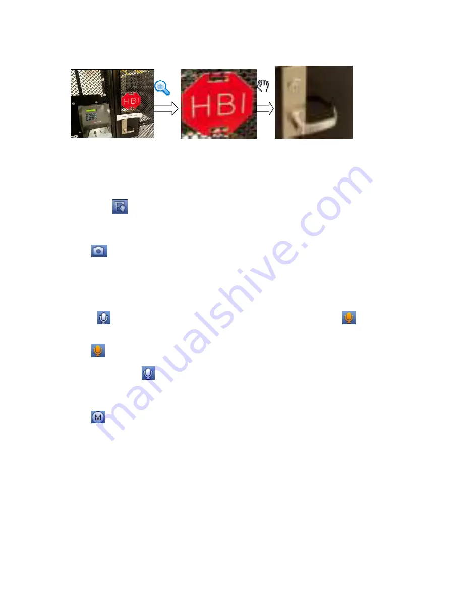
Put the middle button at the centre of the zone you want to zoom in, and move the mouse, user
may view an interface shown as in Figure 3-33.
Figure 3-33
Right click mouse to cancel zoom and go back to the original interface.
3) Manual record function
It is to backup the video of current channel to the USB device. System can not backup the video of
multiple-channel at the same time.
Click button
, system begins recording. Click it again, system stops recoridng. User may find the
record file on the flash disk.
4) Manual Snapshot
Click
to snapshot 1-5 times. The snapshot file is saved on the USB device or HDD. User may go to
the Search interface (chapter 3.12) to view.
5) Bidirectional talk
If the connected front-end device supports bidirectional talk function, user may click this button. Click
button
to start bidirectional talk function the icon now is shown as
. Now the rest
bidirectional talk buttons of digital channel becomes null too.
Click
again, user may cancel bidirectional talk and the bidirectional talk buttons of other digital
channels become as
.
6) Switch stream
Click
, user may switch between the main stream and the sub stream.
M: M stands for main stream.
S: S stands for sub stream. System supports 3 sub streams (S1/S2/S3). Please refer to chapter
3.11.1.1.
3.6.3
Right Click Menu
After you logged in the device, right click mouse, user may see the short cut menu. Please see Figure
3-34.
Window split mode: User may select window amount and then select channels.
Custom split: It is to set video split mode and displayed channel.
PTZ: Click it to go to PTZ interface. Please refer to chapter 3.8.
Fish eye: It is to set fish eye installation mode and display mode. Please refer to chapter 3.7.
Summary of Contents for DNA3500 Series
Page 2: ...DNA Network Video Recorder User s Manual V 5 2 0...
Page 123: ...110 Figure 3 98 Figure 3 99 Figure 3 100...
Page 135: ...122 Figure 3 116 Click draw button to draw the zone See Figure 3 117...
Page 139: ...126 Figure 3 120 Click Draw button to draw a zone See Figure 3 121 Figure 3 121...
Page 144: ...131 Figure 3 126 Click draw button to draw the zone See Figure 3 127...
Page 158: ...145 Figure 3 139 Figure 3 140...
Page 159: ...146 Figure 3 141 Figure 3 142...
Page 160: ...147 Figure 3 143 Figure 3 144...
Page 162: ...149 Figure 3 146 Figure 3 147...
Page 187: ...174 Figure 3 173 Figure 3 174...
Page 255: ...242 Figure 4 53 Figure 4 54...
Page 256: ...243 Figure 4 55 Figure 4 56...
Page 279: ...266 Figure 4 90 Figure 4 91...
Page 286: ...273 Figure 4 100 Figure 4 101...


