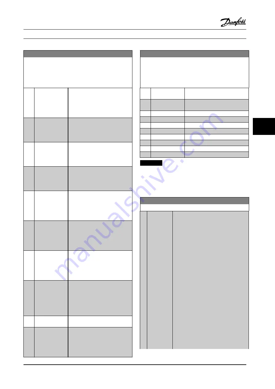
5-40 Function Relay
Array [9]
(Relay 1 [0], Relay 2 [1], Relay 3 [2] (MCB 113), Relay 4 [3] (MCB
113), Relay 5 [4] (MCB 113), Relay 6 [5] (MCB 113), Relay 7 [6]
(MCB 105), Relay 8 [7] (MCB 105), Relay 9 [8] (MCB 105))
Option:
Function:
[123] Start command
activ
Output is high when the start
command is high (via digital input,
bus connection or [Hand on] or [Auto
on]), and a stop has been the last
command.
[124] Running reverse
Output is high when the adjustable
frequency drive is running counter
clockwise (the logical product of the
status bits ‘running’ and ‘reverse’).
[125] Drive in hand
mode
Output is high when the adjustable
frequency drive is in hand on mode
(as indicated by the LED light above
[Hand on]).
[126] Drive in auto
mode
Output is high when the adjustable
frequency drive is in ‘Auto’ mode (as
indicated by LED on above [Auto
On]).
[151] ATEX ETR cur.
alarm
Selectable if
is set to
[20] ATEX
ETR
or
[21] Advanced ETR
. If the alarm
164 ATEX ETR cur.lim.alarm is active,
the output is 1.
[152] ATEX ETR freq.
alarm
Selectable if
is set to
[20] ATEX
ETR
or
[21] Advanced ETR
. If the alarm
166 ATEX ETR freq.lim.alarm is active,
the output is 1.
[153] ATEX ETR cur.
warning
Selectable if
is set to
[20] ATEX
ETR
or
[21] Advanced ETR
. If the alarm
163 ATEX ETR cur.lim.warning is
active, the output is 1.
[154] ATEX ETR freq.
warning
Selectable if
is set to
[20] ATEX
ETR
or
[21] Advanced ETR
. If the
warning 165 ATEX ETR
freq.lim.warning is active, the output
is 1.
[188] AHF Capacitor
Connect
[189] External Fan
Control
The internal logics for the internal fan
control is transferred to this output to
make it possible to control an
external fan (relevant for HP duct
cooling).
5-40 Function Relay
Array [9]
(Relay 1 [0], Relay 2 [1], Relay 3 [2] (MCB 113), Relay 4 [3] (MCB
113), Relay 5 [4] (MCB 113), Relay 6 [5] (MCB 113), Relay 7 [6]
(MCB 105), Relay 8 [7] (MCB 105), Relay 9 [8] (MCB 105))
Option:
Function:
[190] Safe Function
active
[191] Safe Opt. Reset
req.
[192] RS Flipflop 0
[193] RS Flipflop 1
[194] RS Flipflop 2
[195] RS Flipflop 3
[196] RS Flipflop 4
[197] RS Flipflop 5
[198] RS Flipflop 6
[199] RS Flipflop 7
NOTICE!
Set switches S201 (A53) and S202 (A54) as specified in
this section when performing a control card test in
parameter 14-22 Operation Mode
. Otherwise, the test
fails.
14-22 Operation Mode
Option:
Function:
Use this parameter to specify normal
operation, perform tests, or initialize all
parameters except
15-03 Power-ups
,
15-04 Over Temps
and
15-05 Over Volts
. This
function is active only when the power is
cycled to the adjustable frequency drive.
Select
[0] Normal operation
for normal
operation of the adjustable frequency drive
with the motor in the selected application.
Select
[1] Control card test
to test the analog
and digital inputs and outputs and the +10 V
control voltage. The test requires a test
connector with internal connections. To
perform the control card test:
1.
Select
[1] Control card test
.
2.
Disconnect the line power supply
and wait for the light in the display
to go out.
3.
Set switches S201 (A53) and S202
(A54) = ‘ON’/I.
4.
Insert the test plug.
5.
Connect to the line power supply.
Programming
Instruction Manual
MG37A222
Danfoss A/S © Rev. 2014-02-07 All rights reserved.
75
6
6
Summary of Contents for VLT AutomationDrive FC 302
Page 2: ......


