


Hostname
is the cabinet, system, or partition ID; examples include
c0-0
(for a cabinet),
S0
(for a
system), or
p0
(for a partition).
b. For cabinets, place main circuit breakers CB1 and CB2 in the OFF (down) position.
c. For blower cabinets, place the MAIN DISCONNECT switch on the rear panel of the blower cabinet PDU
in the OFF (down) position.
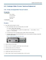
Figure 81. Circuit Breakers for Cabinet (left) and Blower (right)
2. Open the rear door of the cabinet.
3. Unplug the temperature sensor that needs to be replaced.
Location P10 is the supply sensor and location P11 is the return sensor. Note what pipe the old sensor is
attached to so the new temperature sensor is labeled appropriately.
4.
CAUTION:
●
Personal injury
●
Use caution when cutting the foam with the utility knife. Failure to use caution can cause personal
injury.
Cut the foam insulation covering the old temperature sensor using an utility knife and remove it.
Use the new temperature sensor to estimate how much foam to remove. The opening should be
approximately 0.5-cm to 1.5-cm larger than the sensor.
5. Peel off the old temperature sensor from the bare metal piping.
6.
CAUTION:
●
Personal injury
●
Use caution when removing debris with the chissel. Failure to use caution can cause personal
injury.
Remove any large pieces of foam from the metal piping with a chissel.
7. Use sandpaper to remove any remaining debris.
8. Wipe the pipe clean using a clean rag.
System Cabinet Procedures
89