


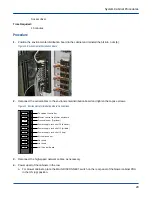


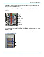


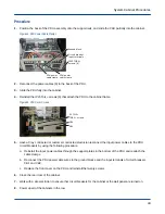


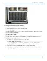


16. Loosen the screws (4) that secure each electrical network alignment block to the chassis on each side of the
backplane.
Figure 25. Guide Block Screws
4 screws
Alignment
block
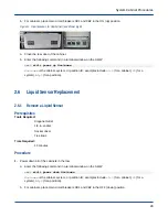
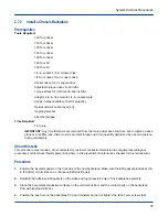
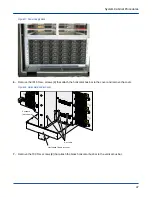
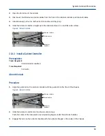
17. After all the EMI blocks have been loosened on both side of the backplane, install the alignment blade in each
slot, and then tighten the associated electrical network alignment block screws (4).
Figure 26. Alignment Blade Tool
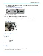
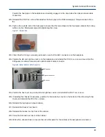
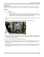
18. Inspect the heat pipes to ensure that the thermal pad is properly positioned and there are no wrinkles or
raised edges. If the thermal pad is attached to the chilled-water pipe in the cabinet, carefully remove the pad
and place it on the heat pipe.
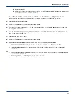
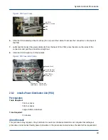
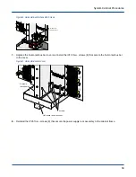
19.
ATTENTION:
●
Equipment Damage
●
The heat pipes are very soft and can be easily bent or damaged.
System Cabinet Procedures
39