

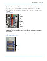


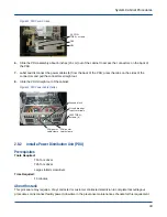


Figure 37. Power Supply Rack
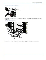
6. Remove the IP15 Torx+ screws (8) that attach the horizontal bus bar to the cover and remove the cover.
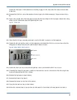
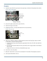
Figure 38. Horizontal Bus Bar Cover
C0S9
C0S8
C0S4
C0S3
C0S2
C0S1
C0S0
J25
J23
J6
J7
J8
J9
J10
J1
J2
J3
J4
J5
4 screws
4 screws
(not shown)
Horizontal bus bar cover
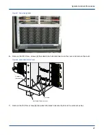
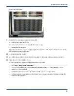
7. Remove the T30 Torx screws (8) that attach the black horizontal bus bar to the vertical bus bar.
System Cabinet Procedures
47