


Time Required:
15 minutes
About this task
This installation procedure is the same for the original and redesigned coil control boards on XC30-LC and XC40-
LC systems.
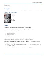
Figure 69. Original and New Coil Control Boards
Original coil
control boa rd
New coil
control boa rd
Procedure
1. Position the coil control board in the cabinet and reinstall the 5/16-in. nuts (4).
2. Reconnect the serial cable to the coil control board and tighten the captive screws.
3. Reconnect the control cables to the coil control board.
●
P6: Environmental distribution board
●
P1: Temperature sensors
●
P3: Moisture sensor
●
P5: Actuator
●
P2: Transducer
4. Reconnect the high-speed network cables removed to access the coil control board.
5. Work with a site electrician to ensure that circuit breakers for the cabinet at the wall panel are turned on.
6. Power up all of the cabinets in the row.
a. For blower cabinets, place the MAIN DISCONNECT switch on the rear panel of the blower cabinet PDU
in the ON (up) position.
b. For cabinets, place main circuit breakers CB1 and CB2 in the ON (up) position.
System Cabinet Procedures
74