


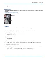


c. For blower cabinets, place the MAIN DISCONNECT switch on the rear panel of the blower cabinet PDU
in the OFF (down) position.
Figure 68. Circuit Breakers for Cabinet (left) and Blower (right)
3. Wait 30 to 40 seconds for the rectifiers to discharge so cables can be safely disconnected.
The rectifiers are discharged when the operator interface panel goes dark.
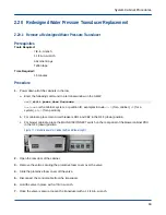
4. Open the rear door of the cabinet.
5. Disconnect any high-speed network cables required to access the coil control board and label all cables.
6. Loosen the small captive Phillips screws (2) that secure the serial cable to the coil control board and
disconnect the cable.
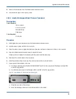
Serial cable
Coil control board
Control cables
4 nuts
7. Label any control cables with missing labels.
8. Disconnect the control cables from the coil control board.
9. Remove the 5/16-in. nuts (4) that attach the coil control board to the cabinet and remove the coil control
board.
2.17.2 Install a Coil Control Board
Prerequisites
Tools Required:
Small Phillips screwdriver
Slotted screwdriver
5/16-in. socket
Socket driver
System Cabinet Procedures
73