


●
This procedure is affected by the current power consumption and utilization of the system. Be
cautious of workload increases or decreases. Significant workflow changes that occur after the
system is in manual mode could lead to cabinet EPO and/or condensation.
Procedure
1. Power down all of the cabinets in the row.
a. Enter the following command in a terminal window on the SMW:
smw$
xtcli power down Hostname
Hostname
is the cabinet, system, or partition ID; examples include
c0-0
(for a cabinet),
S0
(for a
system), or
p0
(for a partition).
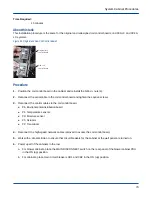
b. For cabinets, place main circuit breakers CB1 and CB2 in the OFF (down) position.
c. For blower cabinets, place the MAIN DISCONNECT switch on the rear panel of the blower cabinet PDU
in the OFF (down) position.
Figure 71. Circuit Breakers for Cabinet (left) and Blower (right)
2. Open the rear door of the cabinet.
3. If necessary, cut the tie straps that secure the water valve actuator cable to the adjacent control cables.
4. Verify the water valve is in the fully closed position.
5. Place a long piece of tape over the actuator indicator dial to hold it in place.
6. Pull on the water valve actuator handle to disconnect the handle from the actuator.
7. Remove the hex-head screw that attaches the actuator to the valve and remove the actuator.
Use the tool on the end of the actuator handle to remove the screw.
8. Disconnect the water valve actuator control cable from the coil control board.
System Cabinet Procedures
76