


●
Electrical hazard
●
Make sure that the electrical circuit breaker for the cabinet is off, locked, and tagged. Failure to do
so could result in severe shock and burns.
Work with a site electrician to ensure that circuit breakers for the cabinet at the wall panel are off. Use
appropriate lockout/tagout or other site-specific procedures to indicate that the breakers are off.
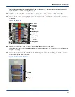
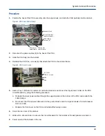
3. Open the front door of the cabinet.
4. Locate the chassis with the defective backplane assembly.
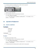
5. Slide all of the blades approximately 2 inches out from the front of the chassis to disconnect the blades from
the backplane connectors.
6. Slide the chassis host approximately 2 inches out from the front of the chassis to disconnect the chassis host
from the backplane connectors.
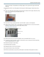
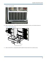
7. Open the rear door of the cabinet.
8. Locate the chassis with the defective backplane assembly.
9. Label, disconnect, and install protective covers on all of the high-speed network cables.
a. Disconnect the cables from adjacent chassis as necessary to access the defective backplane.
b. Place protective covers on the copper network cable connector plugs and on the ends of the optical
network cables.
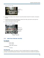
10.
●
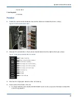
If removing the chassis 0 backplane, remove the IP15 Torx+ screws (8) that attach the horizontal bus bar
cover and remove the cover.
●
If removing chassis 1 or 2 backplane, proceed to the next step.
System Cabinet Procedures
33