


Procedure
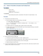
1. Peel off the adhesive backing from the new temperature sensor and place the sensor on the bare pipe.
2.
CAUTION:
●
Personal injury
●
Use caution when cutting the foam with the utility knife. Failure to do so can result in personal
injury.
Cut a piece of adhesive foam insulation to cover the new temperature sensor. Make the piece the same size
as the hole cut in the foam.
3. Remove the foam adhesive and place the piece of adhesive foam over the new temperature sensor.
4. Continue to add foam until the foam over the temperature sensor is flush with the remaining foam.
5. Label the temperature sensor connector to match the label on the old temperature sensor.
6. Coil the temperature sensor cables and secure them to the water line with Velcro or tape. Leave enough wire
to plug the temperature sensor connectors into the coil control board.
7. Connect the new temperature sensor to the same location as the old temperature sensor.
Location P10 is the supply sensor and location P11 is the return sensor.
8. Replace the EMI filter side panel.
a. Lift the side panel and position it in the lower lip of the cabinet.
b. Push the side panel up against the cabinet.
c. Turn the top two quarter-turn fasteners with a 5/16-in. balldriver wrench.
d. Turn the four remaining quarter-turn fasteners with a 5/32-in. balldriver wrench to close the side panel.
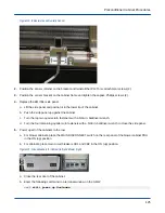
9. Power up all of the cabinets in the row.
a. For blower cabinets, place the MAIN DISCONNECT switch on the rear panel of the blower cabinet PDU
in the ON (up) position.
b. For cabinets, place main circuit breakers CB1 and CB2 in the ON (up) position.
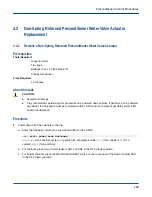
Figure 114. Circuit Breakers for Cabinet (left) and Blower (right)
a. Close the rear door of the cabinet.
b. Enter the following command in a terminal window on the SMW:
Preconditioner Cabinet Procedures
120