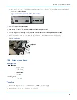


Procedure
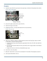
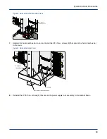
1. Position the back of the PDU assembly onto the support rails, and slide the PDU partially into the cabinet.
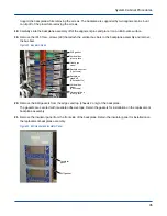
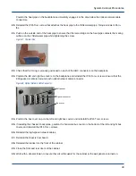
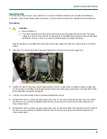
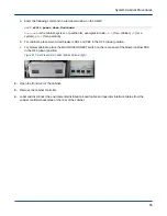
Figure 33. PDU Power Cable Clamps
Ground block
Circuit breaker
input terminals
IP25 TORX+
screws (6)
PDU power
cable clamp
PDU power
cable clamp
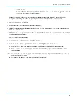
2. Reconnect the power cables (6) to the back of the PDU.
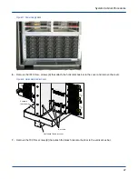
3. Slide the PDU fully into the cabinet.
4. Reinstall the IP25 Torx+ screws (6) that attach the PDU to the cabinet frame.
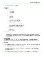
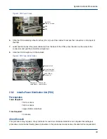
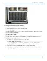
Figure 34. PDU Cover Screws
20 IP15+
TORX+ screws
CB2
CB1
5. Have a Cray contracted or customer contracted electrician reconnect the input power cables to the PDU
circuit breakers by using the following procedure:
a. Reinstall the input power cables through the support plates in the bottom of the PDU and reattach the
cable clamps.
b. Reconnect the PDU power cable wires to the ground blocks and the input terminals of circuit breakers
CB1 and CB2.
c. Replace the front cover on the PDU and reinstall the twenty screws.
6. Close the rear door of the cabinet.
7. Work with a site electrician to ensure that circuit breakers for the cabinet at the wall panel are turned on.
8. Power up all of the cabinets in the row.
System Cabinet Procedures
44