


Procedure
1. Position the liquid sensor in the cabinet and reinstall the 1/4-in. nuts (2).
2. Reconnect the control cable to the coil control board.
3. Replace the tie straps that secure the control cables.
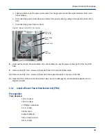
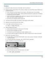
Figure 101. Liquid Sensor
Liquid sensor
2 nuts
4. Replace the EMI filter side panel.
a. Lift the side panel and position it in the lower lip of the cabinet.
b. Push the side panel up against the cabinet.
c. Turn the top two quarter-turn fasteners with a 5/16-in. balldriver wrench.
d. Turn the four remaining quarter-turn fasteners with a 5/32-in. balldriver wrench to close the side panel.
5. Power up all of the cabinets in the row.
a. For blower cabinets, place the MAIN DISCONNECT switch on the rear panel of the blower cabinet PDU
in the ON (up) position.
b. For cabinets, place main circuit breakers CB1 and CB2 in the ON (up) position.
Figure 102. Circuit Breakers for Cabinet (left) and Blower (right)
a. Close the rear door of the cabinet.
b. Enter the following command in a terminal window on the SMW:
smw$
xtcli power up Hostname
Hostname
is the cabinet, system, or partition ID; examples include
c0-0
(for a cabinet),
S0
(for a
system), or
p0
(for a partition).
Preconditioner Cabinet Procedures
105