


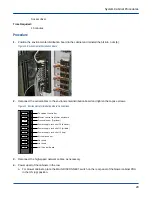


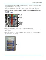


c. For blower cabinets, place the MAIN DISCONNECT switch on the rear panel of the blower cabinet PDU
in the OFF (down) position.
Figure 14. Circuit Breakers for Cabinet (left) and Blower (right)
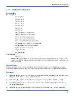
2. Open the rear door of the cabinet.
3. Disconnect the liquid sensor control cable from the coil control board.
4. If necessary, cut the tie straps that secure the liquid sensor cable to the adjacent control cables.
5. Remove the 1/4-in. nuts (2) that attach the liquid sensor to the cabinet and remove the sensor.
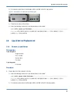
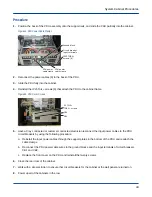
Figure 15. Liquid Sensor
Liquid sensor
2 nuts
2.6.2
Install a Liquid Sensor
Prerequisites
Tools Required:
Diagonal cutter
1/4-in. socket
Socket driver
Tie straps
Time Required:
15 minutes
Procedure
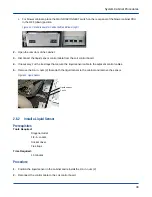
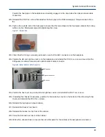
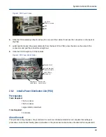
1. Position the liquid sensor in the cabinet and reinstall the 1/4-in. nuts (2).
2. Reconnect the control cable to the coil control board.
System Cabinet Procedures
30