


Hostname
is the cabinet, system, or partition ID; examples include
c0-0
(for a cabinet),
S0
(for a
system), or
p0
(for a partition).
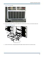
b. For cabinets, place main circuit breakers CB1 and CB2 in the OFF (down) position.
c. For blower cabinets, place the MAIN DISCONNECT switch on the rear panel of the blower cabinet PDU
in the OFF (down) position.
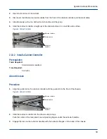
Figure 52. Circuit Breakers for Cabinet (left) and Blower (right)
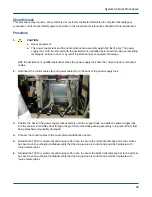
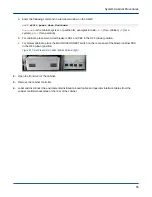
2. Open the front door of the cabinet.
3. Disconnect the SMW ethernet cables and side band cables.
4. Remove the cabinet controller.
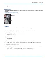
5. Remove the T15 Torx screws (11) that attach the shroud to the cabinet controller and remove the shroud.
6. Simultaneously push out on both DIMM cams with thumbs to eject the DIMM from the socket.
7. Remove the DIMM and place it on an ESD-safe surface.
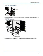
Figure 53. Cabinet Controller DIMM
2.12.2 Install a Cabinet Controller DIMM
Prerequisites
Tools Required:
T15 Torx bit
Adjustable torque driver, 5-40 in-lbs
Small slotted screwdriver
System Cabinet Procedures
59