


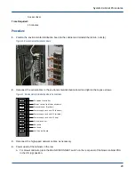


3. Replace the tie straps that secure the control cables, if necessary.
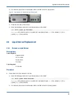
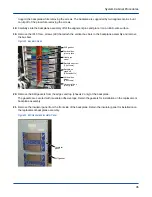
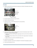
Figure 16. Liquid Sensor
Liquid sensor
2 nuts
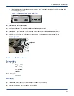
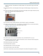
4. Power up all of the cabinets in the row.
a. For blower cabinets, place the MAIN DISCONNECT switch on the rear panel of the blower cabinet PDU
in the ON (up) position.
b. For cabinets, place main circuit breakers CB1 and CB2 in the ON (up) position.
Figure 17. Circuit Breakers for Cabinet (left) and Blower (right)
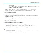
a. Close the rear door of the cabinet.
b. Enter the following command in a terminal window on the SMW:
smw$
xtcli power up Hostname
Hostname
is the cabinet, system, or partition ID; examples include
c0-0
(for a cabinet),
S0
(for a
system), or
p0
(for a partition).
2.7
Chassis Backplane Replacement
2.7.1
Remove a Chassis Backplane
Prerequisites
Tools Required:
T10 Torx driver
T15 Torx driver
T20 Torx driver
System Cabinet Procedures
31