


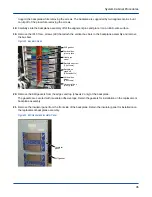


5. If installing the chassis 0 backplane, clean the bare metal conductive surfaces on the horizontal bus bars on
the backplane and the cabinet with isopropyl alcohol.
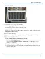
6. Position the backplane onto the alignment pins on the chassis frame.
If installing chassis 2, ensure that the EMI gaskets on the sides and top of the backplane are properly
positioned between the backplane assembly and the cabinet frame.
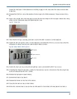
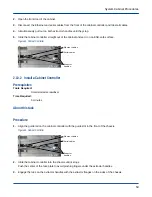
7. Reinstall, then hand tighten, the 1/4-in. (28) standoffs that attach the backplane to the chassis.
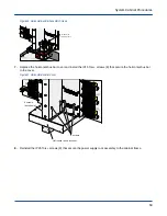
8. Reinstall, but do not tighten, the IP20 Torx+ screws (16) that attach the backplane to the chassis.
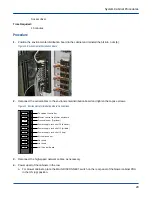
Figure 24. Standoff and Screw Positions
16 screws
28 standoffs
9. Torque the 1/4-in. standoffs and IP20 screws to 14 in-lbs.
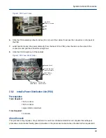
10. Clean the bare metal conductive surfaces on the vertical bus bars and the joiner plates with isopropyl alcohol.
Make sure the orientation of the conical washers is such that the washers compress when the bolts are
tightened.
11. Position the joiner plates on the vertical buses and reinstall, but do not tighten, the 7/16-in. nuts (20).
Chassis 0 and 2 have one set of plates; chassis 1 has two sets of plates.
12. If installing the chassis 0 backplane, position the joiner plates on the horizontal buses and reinstall, but do not
tighten the IP30 Torx+ screws (16).
13.
WARNING:
●
Equipment Damage
●
Failure to properly torque all nuts and bolts will damage the bus bar or back plane.
Torque the IP10 vertical bus bar screws (48) to 6 in-lbs. Have another person verify that the torque value is
correct and paint the hardware with torque marker paint.
14. Torque the 7/16-in. vertical bus bar joiner plate nuts (20) to 75 in-lbs. Have another person verify that the
torque value is correct and paint the hardware with torque marker paint.
15. Torque the IP30 Torx+ horizontal bus bar joiner plate screws (16) to 95 in-lbs. Have another person verify that
the torque value is correct and paint the hardware with torque marker paint.
System Cabinet Procedures
38