INSTALLATION AND SETUP
Cine-IPM 2K User’s Manual
2-9
020-100164-01 Rev. 1 (01/08)
All input signals processed by the
Cine-IPM 2K
are routed to the identical DVI
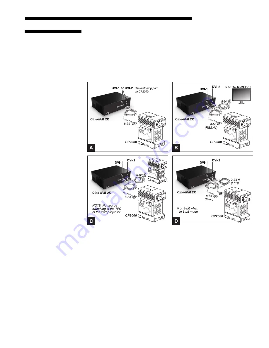
outputs located on the rear panel of the unit. Connect
DVI-1
to the
DVI-1
connector on
the
CP2000
(cable provided). If desired, connect an additional display device such as
a digital monitor using
DVI-2
. Shown are 4 typical applications for the
Cine-IPM 2K
:
• 8-bit mode for one
CP2000
(Figure 2.12A)
• 8-bit mode for
CP2000
and a digital monitor (Figure 2.12B)
• 8-bit mode for two
CP2000s
(Figure 2.12C)
• 8-bit or 10-bit mode for one
CP2000
(Figure 2.12D)
Figure 2.12. Connecting for 8-bit vs. 10-bit Use
If desired, such as when you have digital progressive source data, you can output it in
10-bit format for a single
CP2000
connected to the
Cine-IPM 2K
. This is shown in
Figure 2.12D above. Because
Cine-IPM 2K’s
10-bit output is divided between the
two DVI ports, with
DVI-1
handling the most-significant 8 bits and
DVI-2
handling the
remaining least-significant 2 bits, 10-bit mode requires
both
outputs connected to the
corresponding
CP2000
DVI
ports.
Selecting 8-bit or 10-bit Mode
With the Figure 2.12D configuration, you can use either 8-bit or 10-bit
Cine-IPM 2K
mode for all sources. Make sure to set this mode (a.k.a. “Data Format”) in 2 places:
2.3 Connecting
DVI
Outputs
Connecting
for
X
10-bit
Use
Summary of Contents for CineIPM-2K
Page 1: ...CineIPM 2K U S E R S M A N U A L 020 100164 01...
Page 2: ......
Page 26: ......
Page 108: ......
Page 110: ......
Page 112: ...SERIAL COMMUNICATION CABLES C 2 Cine IPM 2K User s Manual 020 100164 01 Rev 1 01 08...
Page 118: ......


