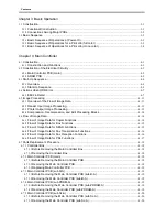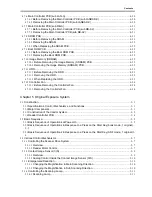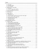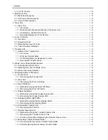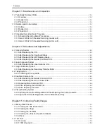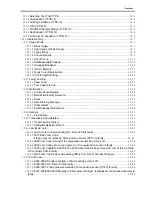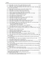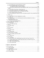
Contents
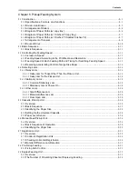
15.3.7.5
E013-0002: Connector of DC Controller PCB has poor contact
......................................... 15- 45
15.3.7.6
E020-0010 occurred upon installation: ATR shutter comes off
........................................... 15- 45
E020-0013 is displayed after message "Reservation copies can be made." is displayed upon
.............................................................................................................. 15- 46
15.3.7.8
E020-0023/This machine fails to start: Bk drum cartridge is faulty
..................................... 15- 46
15.3.7.9
E020-0200: Connector at Process unit has poor contact
..................................................... 15- 47
15.3.7.10
E025-0003: Toner rotation volume sensor (PS6) is soiled
................................................ 15- 47
15.3.7.11
E025: Connector of process kit relay PCB has poor contact
............................................. 15- 47
15.3.7.12
E045 is displayed during startup after power-on: OHT sensor unit is faulty
................... 15- 47
15.3.7.13
E067-0102: DC Controller PCB has poor contact
............................................................... 15- 47
15.3.7.14
E110-0000: Laser scanner assembly is faulty
..................................................................... 15- 48
15.3.7.15
E193-0001: DC driver PCB is faulty
...................................................................................... 15- 48
15.3.7.16
E225-0001/scanning lamp does not come on: Inverter PCB is faulty
.............................. 15- 48
15.3.7.17
E227-0001: Controller power supply PCB is faulty
............................................................. 15- 48
15.3.7.18
E227-0001: Printer Power Supply PCB is faulty
.................................................................. 15- 48
15.3.7.19
E240-0002/rebooting/this machine hangs up with message "Printing"
........................... 15- 49
15.3.7.20
E244-0001: Flexible cable of DC controller PCB has poor contact
.................................. 15- 49
15.3.7.21
E315-000E/E611-0001 occurs when sending certain data from PC as FAX message
15- 49
15.3.7.22
E351-0000 is displayed at start-up after power-on
15.3.7.23
E532-8002: Sensor lever of Finisher-Z1 causes malfunction
............................................ 15- 49
15.3.7.24
E532-8001/E532-8002: Finisher Controller of Finisher-Z1 is faulty
................................. 15- 50
15.3.7.25
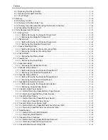
E532-8002: Connector of stapler shift motor (M105) found in Saddle Finisher-Y2 has poor
.................................................................................................................................................... 15- 50
15.3.7.26
E602-0001: Main controller PCB is faulty
............................................................................. 15- 50
15.3.7.27
E602-0113: HDD (hard disk) is faulty
.................................................................................... 15- 51
15.3.7.28
E602-0002: Main Controller PCB (sub LANBER-C) is faulty
............................................. 15- 51
15.3.7.29
............................................................................................ 15- 51
15.3.7.30
E611-0000 occurs during startup (upon installation): SRAM PCB is faulty
..................... 15- 51
15.3.7.31
E674-0001/FAX function of Super G3 FAX Board-W1 does not work: Main controller PCB
....................................................................................................................................... 15- 51
15.3.7.32
E350-0000/E732-0001/E747-051B/E747-DF00/E748-4000: Sub SJ-A board has poor
................................................................................................................................. 15- 52
15.3.7.33
E732-0001/E811-0001 occurs upon installation: Connector J254 hs poor contact
....... 15- 52
15.3.7.34
E732-9999 is displayed after mounting scanner
................................................................. 15- 52
15.3.7.35
E747/E748: Procedure for mounting Sub when poor contact occurs
.............................. 15- 52
15.3.7.36
E747-C000 is displayed at copying because paper jam occurs in front of registration area:
............................................................................................................................. 15- 52
15.3.7.37
E747-0719/E747-051b/E747-0619/E747-621f/this machine fails to start upon installation:
............................................................................................................... 15- 53
15.3.7.38
E747-221D/E747-221F/E747-381B/E747-421D/E747-C000/E747-C51D: Image memory
................................................................................................................................. 15- 53
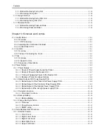
15.3.7.39
E747-3619: Main controller PCB (main) is faulty
................................................................. 15- 53
15.3.7.40
E747-0219 occurs when selecting Image Repeat > Area Designation (or Flaming) > Copy
........................................................................................................................................................ 15- 53
15.3.7.41
E748-4031/long start-up time and progress bar stops at point of one-twentieth although
these symptoms are temporarily solved by powering OFF/ON:
15.3.7.42
E748-4000: Voltage of power supplied to this machine drops
.......................................... 15- 54
15.3.7.43
E748-4000: Main controller PCB (main) is faulty
................................................................. 15- 54
: Main Controller PCB (SJ-A) is faulty
. ............................................................................................................15- 49
Hard Disk Drive (HDD) is faulty
............................................................................................................................................15- 54
Summary of Contents for CiRC2550
Page 2: ......
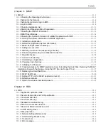
Page 27: ...Chapter 1 Introduction ...
Page 28: ......
Page 47: ...Chapter 1 1 18 F 1 14 ON OFF ON OFF ...
Page 70: ...Chapter 1 1 41 5 Turn on the main power switch ...
Page 79: ...Chapter 2 Installation ...
Page 80: ......
Page 85: ...Chapter 2 2 3 Not available in some regions ...
Page 134: ...Chapter 3 Basic Operation ...
Page 135: ......
Page 137: ......
Page 143: ...Chapter 4 Main Controller ...
Page 144: ......
Page 152: ...Chapter 4 4 6 F 4 6 CPU HDD ROM access to the program at time of execution ...
Page 171: ...Chapter 5 Original Exposure System ...
Page 172: ......
Page 203: ...Chapter 6 Laser Exposure ...
Page 204: ......
Page 206: ......
Page 220: ...Chapter 7 Image Formation ...
Page 221: ......
Page 277: ...Chapter 8 Pickup Feeding System ...
Page 278: ......
Page 282: ......
Page 336: ...Chapter 9 Fixing System ...
Page 337: ......
Page 339: ......
Page 357: ...Chapter 10 Externals and Controls ...
Page 358: ......
Page 362: ......
Page 366: ...Chapter 10 10 4 F 10 2 F 10 3 FM1 FM2 FM5 FM8 FM11 FM4 FM3 FM6 FM7 FM9 FM10 ...
Page 375: ...Chapter 10 10 13 F 10 10 2 Remove the check mark from SNMP Status Enabled ...
Page 376: ...Chapter 10 10 14 F 10 11 ...
Page 402: ...Chapter 11 MEAP ...
Page 403: ......
Page 405: ......
Page 452: ...Chapter 12 RDS ...
Page 453: ......
Page 455: ......
Page 464: ...Chapter 13 Maintenance and Inspection ...
Page 465: ......
Page 467: ......
Page 469: ...Chapter 13 13 2 F 13 1 8 9 1 2 3 3 5 6 7 10 11 12 13 14 4 ...
Page 474: ...Chapter 14 Standards and Adjustments ...
Page 475: ......
Page 477: ......
Page 485: ......
Page 486: ...Chapter 15 Correcting Faulty Images ...
Page 487: ......
Page 495: ...Chapter 15 15 4 F 15 2 COLOR M 1 COLOR Y C K 0 ...
Page 569: ...Chapter 15 15 78 F 15 82 J102 J107 J103 J108 J101 J109 J106 J112 J115 J113 J114 J104 J105 ...
Page 570: ...Chapter 16 Self Diagnosis ...
Page 571: ......
Page 573: ......
Page 600: ...Chapter 17 Service Mode ...
Page 601: ......
Page 603: ......
Page 712: ...Chapter 18 Upgrading ...
Page 713: ......
Page 715: ......
Page 746: ...Chapter 19 Service Tools ...
Page 747: ......
Page 749: ......
Page 752: ...APPENDIX ...
Page 774: ......

