


Chapter 17
17-57
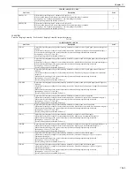
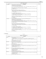
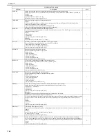
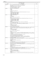
9. MISC-R
T-17-49
10. MISC-P
MN-CON
Clears RAM on main controller PCB's SRAM board.
Attention:
- The RAM is cleared after the OK key is pressed.
- Performing this item initializes all the data on the SRAM board. In other words, file management information for the
hard disk is initialized, and image data on the hard disk can no longer be read. Before performing this item, explain to
the user that all images in the BOX will be lost, and receive permission to perform.
Operation method
1) Select COPIER > FUNCTION > MISC-P > P-PRINT to print out the service mode setting values.
2) Select this item, then press the OK key.
1
CARD
Clears card ID (department) data.
Attention:
The card ID data is cleared after the main power switch is turned OFF/ON.
Operation method
1) Select this item, then press the OK key.
2) Turn the main power OFF/ON.
1
LANG-ERR
Clear language related error.
This item enables recovery when a language related error code is generated after switching from the default language.
(Returns to default language after recovery.)
1
ERDS-DAT
Embedded-RDS SRAM data clear
SCM data in the embedded-RDS SRAM are restored to the factory settings.
1
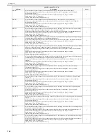
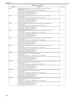
Y-TN-CLR
Y color toner counter clear
This clears the Y color toner counter.
Clear the counter when the toner cartridge has been replaced before the toner runs out after the low remaining Y color
toner warning has been given. To specify the counter to be cleared, execute COUNTER>MISC>T-SPLY-Y.
1
M-TN-CLR
M color toner counter clear
This clears the M color toner counter.
Clear the counter when the toner cartridge has been replaced before the toner runs out after the low remaining M color
toner warning has been given. To specify the counter to be cleared, execute COUNTER>MISC>T-SPLY-M.
1
C-TN-CLR
C color toner counter clear
This clears the C color toner counter.
Clear the counter when the toner cartridge has been replaced before the toner runs out after the low remaining C color
toner warning has been given. To specify the counter to be cleared, execute COUNTER>MISC>T-SPLY-C.
1
K-TN-CLR
K color toner counter clear
This clears the K color toner counter.
Clear the counter when the toner cartridge has been replaced before the toner runs out after the low remaining K color
toner warning has been given. To specify the counter to be cleared, execute COUNTER>MISC>T-SPLY-K.
1
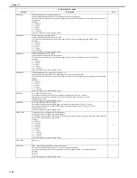
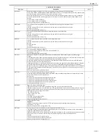
SND-STUP
- use it to initialize the transmission read settings
After changing service mode settings (pressing the OK key), turn off and then on the power to initialize the backup data
of the transmission read settings.
Otherwise, after you have changed the display language, the language used before the change would remain. Be sure to
perform this mode item if you have switched the language.
2
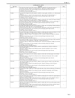
CA-KEY
CA authentication and key deleted together.
When the serviceman needs to replace or dispose of the device, the CA authentication and key can be deleted together.
2
KEY-CLR
HDD encoding board code key clear
The HDD encoding board (security kit) code key is cleared to allow replacement.
When this item is selected and OK pressed, the code key is cleared. Then, when the main power supply is turned OFF/
ON, the encoding board installation processing activates. If installation processing is carried out, a new code key is
generated.
Caution!
If this operation is carried out, all data on the HDD will be rendered useless. The main power supply is switched OFF/
ON after this operation in order to format the HDD.
2
REG-CLR
Color displacement adjustment value clear
In the case that the value adjusted by color displacement control is abnormal due to some causes, clear the adjustment
value and return it to the initial state.
Use Case
In the case that color displacement of YMCK occurs and it cannot be corrected, clear the adjustment value in this mode.
How to Use
1) Clear the auto registration adjustment value using this service mode.
2) Turn off/ on, or execute the following item; Auto gradation adjustment > Quick adjust.
2
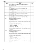
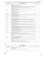
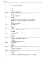
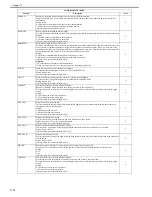
COPIER>FUNCTION>MISC-R
Sub item
Description
level.
SCANLAMP
Use it to check the activation of the scanning lamp.
Method of Operation
1) Select the item.
2) Press the OK key so that the scanning lamp will go on and remain on for 3 sec.
1
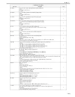
COPIER>FUNCTION>CLEAR
Sub item
Description
level.
Summary of Contents for CiRC2550
Page 2: ......
Page 27: ...Chapter 1 Introduction ...
Page 28: ......
Page 47: ...Chapter 1 1 18 F 1 14 ON OFF ON OFF ...
Page 70: ...Chapter 1 1 41 5 Turn on the main power switch ...
Page 79: ...Chapter 2 Installation ...
Page 80: ......
Page 85: ...Chapter 2 2 3 Not available in some regions ...
Page 134: ...Chapter 3 Basic Operation ...
Page 135: ......
Page 137: ......
Page 143: ...Chapter 4 Main Controller ...
Page 144: ......
Page 152: ...Chapter 4 4 6 F 4 6 CPU HDD ROM access to the program at time of execution ...
Page 171: ...Chapter 5 Original Exposure System ...
Page 172: ......
Page 203: ...Chapter 6 Laser Exposure ...
Page 204: ......
Page 206: ......
Page 220: ...Chapter 7 Image Formation ...
Page 221: ......
Page 277: ...Chapter 8 Pickup Feeding System ...
Page 278: ......
Page 282: ......
Page 336: ...Chapter 9 Fixing System ...
Page 337: ......
Page 339: ......
Page 357: ...Chapter 10 Externals and Controls ...
Page 358: ......
Page 362: ......
Page 366: ...Chapter 10 10 4 F 10 2 F 10 3 FM1 FM2 FM5 FM8 FM11 FM4 FM3 FM6 FM7 FM9 FM10 ...
Page 375: ...Chapter 10 10 13 F 10 10 2 Remove the check mark from SNMP Status Enabled ...
Page 376: ...Chapter 10 10 14 F 10 11 ...
Page 402: ...Chapter 11 MEAP ...
Page 403: ......
Page 405: ......
Page 452: ...Chapter 12 RDS ...
Page 453: ......
Page 455: ......
Page 464: ...Chapter 13 Maintenance and Inspection ...
Page 465: ......
Page 467: ......
Page 469: ...Chapter 13 13 2 F 13 1 8 9 1 2 3 3 5 6 7 10 11 12 13 14 4 ...
Page 474: ...Chapter 14 Standards and Adjustments ...
Page 475: ......
Page 477: ......
Page 485: ......
Page 486: ...Chapter 15 Correcting Faulty Images ...
Page 487: ......
Page 495: ...Chapter 15 15 4 F 15 2 COLOR M 1 COLOR Y C K 0 ...
Page 569: ...Chapter 15 15 78 F 15 82 J102 J107 J103 J108 J101 J109 J106 J112 J115 J113 J114 J104 J105 ...
Page 570: ...Chapter 16 Self Diagnosis ...
Page 571: ......
Page 573: ......
Page 600: ...Chapter 17 Service Mode ...
Page 601: ......
Page 603: ......
Page 712: ...Chapter 18 Upgrading ...
Page 713: ......
Page 715: ......
Page 746: ...Chapter 19 Service Tools ...
Page 747: ......
Page 749: ......
Page 752: ...APPENDIX ...
Page 774: ......


