


Chapter 17
17-22
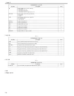
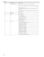
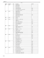
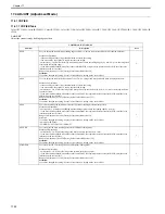
P005
0
AC power supply detection signal
1: 100/120V 0: 200V
1
Thermistor connection detection signal
1: open 0: connected
2
Connection of the flexible cable detection signal
0: connected
3
Power supply fan 2 ON
1: ON 0: OFF
4
Delivery adhesive fan half-speed control
1: ON 0: OFF
5
Fixing exhaust fan R, F (13 V) half-speed control
1: ON 0: OFF
6
Loop sensor
1: ON 0: OFF
7
Cassette level sensor
1: ON 0: OFF
8
CST 2 pick-up motor enable
1: ON 0: OFF
9
Power supply fan 2 half-speed control
1: ON 0: OFF
10
CST 1 pick-up motor enable
1: ON 0: OFF
11
Secondary transfer exhaust fan (13 V) half-speed control
1: ON 0: OFF
12
Toner sensor
1: ON 0: OFF
13
Main thermistor resistance switch
1: low temperature mode 0: high temperature mode
14
Soft relay ON
1: ON 0: OFF
15
Fixing motor enable
1: Enable 0: Disable
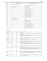
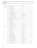
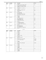
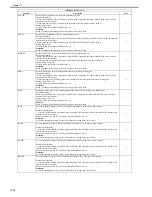
P006
0
Toner CRG (Bk) level sensor
1: Toner present
1
Toner CRG (C) level sensor
1: Toner present
2
Toner CRG (M) level sensor
1: Toner present
3
Toner CRG (Y) level sensor
1: Toner present
4
Toner motor error (Y)
0: Error
5
Toner motor error (M)
0: Error
6
Toner motor error (C)
0: Error
7
Toner motor error (Bk)
0: Error
8
Drum unit old / new sensor signal (K)
0: Detection of new unit
9
Drum unit old / new sensor signal (C)
0: Detection of new unit
10
Drum unit old / new sensor signal (M)
0: Detection of new unit
11
Drum unit old / new sensor signal (Y)
0: Detection of new unit
12
Power supply fan lock signal
0: Whirling
13
Not in use
14
PIT frame sensor (drawer connector connection sensor)
0: In-contact
15
2, 3 delivery door sensor
1: Closed
Address
bit
Description
Remarks
Summary of Contents for CiRC2550
Page 2: ......
Page 27: ...Chapter 1 Introduction ...
Page 28: ......
Page 47: ...Chapter 1 1 18 F 1 14 ON OFF ON OFF ...
Page 70: ...Chapter 1 1 41 5 Turn on the main power switch ...
Page 79: ...Chapter 2 Installation ...
Page 80: ......
Page 85: ...Chapter 2 2 3 Not available in some regions ...
Page 134: ...Chapter 3 Basic Operation ...
Page 135: ......
Page 137: ......
Page 143: ...Chapter 4 Main Controller ...
Page 144: ......
Page 152: ...Chapter 4 4 6 F 4 6 CPU HDD ROM access to the program at time of execution ...
Page 171: ...Chapter 5 Original Exposure System ...
Page 172: ......
Page 203: ...Chapter 6 Laser Exposure ...
Page 204: ......
Page 206: ......
Page 220: ...Chapter 7 Image Formation ...
Page 221: ......
Page 277: ...Chapter 8 Pickup Feeding System ...
Page 278: ......
Page 282: ......
Page 336: ...Chapter 9 Fixing System ...
Page 337: ......
Page 339: ......
Page 357: ...Chapter 10 Externals and Controls ...
Page 358: ......
Page 362: ......
Page 366: ...Chapter 10 10 4 F 10 2 F 10 3 FM1 FM2 FM5 FM8 FM11 FM4 FM3 FM6 FM7 FM9 FM10 ...
Page 375: ...Chapter 10 10 13 F 10 10 2 Remove the check mark from SNMP Status Enabled ...
Page 376: ...Chapter 10 10 14 F 10 11 ...
Page 402: ...Chapter 11 MEAP ...
Page 403: ......
Page 405: ......
Page 452: ...Chapter 12 RDS ...
Page 453: ......
Page 455: ......
Page 464: ...Chapter 13 Maintenance and Inspection ...
Page 465: ......
Page 467: ......
Page 469: ...Chapter 13 13 2 F 13 1 8 9 1 2 3 3 5 6 7 10 11 12 13 14 4 ...
Page 474: ...Chapter 14 Standards and Adjustments ...
Page 475: ......
Page 477: ......
Page 485: ......
Page 486: ...Chapter 15 Correcting Faulty Images ...
Page 487: ......
Page 495: ...Chapter 15 15 4 F 15 2 COLOR M 1 COLOR Y C K 0 ...
Page 569: ...Chapter 15 15 78 F 15 82 J102 J107 J103 J108 J101 J109 J106 J112 J115 J113 J114 J104 J105 ...
Page 570: ...Chapter 16 Self Diagnosis ...
Page 571: ......
Page 573: ......
Page 600: ...Chapter 17 Service Mode ...
Page 601: ......
Page 603: ......
Page 712: ...Chapter 18 Upgrading ...
Page 713: ......
Page 715: ......
Page 746: ...Chapter 19 Service Tools ...
Page 747: ......
Page 749: ......
Page 752: ...APPENDIX ...
Page 774: ......


