


Chapter 17
17-68
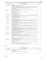
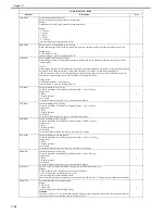
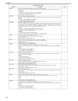
FTPTXPN
Used to specify port (FTP) number to send to.
0 to 65535 (16-bit value)
[Factory default/After RAM clear: 21]
2
PRNT-ORD
Used to switch order of output to side tray.
Whenever possible, avoid using this setting during normal operation.
2
PRN-FLG
Used to select area flag for PDL images.
Whenever possible, avoid using this setting during normal operation.
2
SCN-FLG
Used to select area flag for copy images.
Whenever possible, avoid using this setting during normal operation.
2
T-LW-LVL
Low remaining toner warning message display timing selection
This selects the threshold (%) of the remaining amount of toner at which "Low toner message" is displayed on the control
unit. It is used when selecting the percentage of the toner left at which to display the supply toner warning.
Settings
0: Normal level (5% remaining)
1: 10% remaining
2: 15% remaining
3: 20% remaining
[Factory setting/value after clearing RAM: 0]
Attention:
Every effort must be made to avoid using this when the machine is operating normally.
2
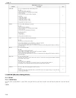
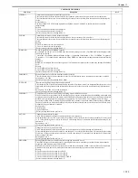
NWERR-SW
Used to select whether to display network error messages.
Setting values
0: Don't display
1: Display
[Factory default/After RAM clear: 1]
2
STS-PORT
ON/OFF of T.O.T (TUIF over TCP/IP) synchronized status communication port
This sets the port used for communicating the Inquiry/Response (synchronized) statuses in T.O.T to ON or OFF.
Settings
0: OFF
1: ON
[Factory setting/value after clearing RAM: 0]
Set this to "1" when using a crossover cable to connect the PC and machine while using service NAVI.
MEMO:
T.O.T (TUIF over TCP)
A communication protocol (unique to Canon) for the presentation of built-in applications (UI) and for communicating
between applications inside the machine such as COPY, SEND and BOX.
2
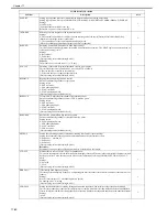
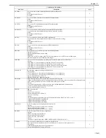
CMD-PORT
ON/OFF of T.O.T (TUIF over TCP/IP) non-synchronized command communication port
This sets the port used for communicating non-synchronized commands in T.O.T to ON or OFF.
Settings
0: OFF
1: ON
[Factory setting/value after clearing RAM: 0]
Set this to "1" when using a crossover cable to connect the PC and machine while using service NAVI.
MEMO:
T.O.T (TUIF over TCP)
A communication protocol (unique to Canon) for the presentation of built-in applications (UI) and for communicating
between applications inside the machine such as COPY, SEND and BOX.
2
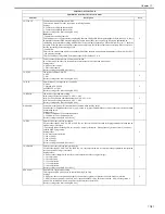
MODELSZ2
Global support with pressure plate document size detection (both AB and inch detection)
When this item is set to "1," the AB/inch (global) support mode is established regardless of the AB/inch switching flag
MODEL-SZ setting.
Settings
0: Normal (no global detection: size detected by AB or inch depending on destination)
1: Both AB and inch series detection (global detection)
[Factory setting/value after clearing RAM: 0]
Attention:
- This is used to support individual users, and it must not be used under normal circumstances.
- In order to detect both the AB and inch series, document size detection sensors are required separately.
2
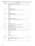
OHP-PTH
Setting of sheet count for executing ITB cleaning sequence after OHP film has passed through
This changes the frequency of the cleaning band inserted into the post rotation and between sheets when OHP film has
passed through.
With some types of OHP film, the substances in the film's conductive layer adhere to the ITB (OHT memory), leaving
areas of the images white. For this reason, the ITB cleaning sequence is executed by the default setting between sheets
or in the post-rotation. Reduce the value if white spots caused by the OHT memory data occurs. If no OHT memory
data is generated, the down time and toner consumption can be reduced by increasing the value.
Setting range:
- Between sheets: Intervals of 0 to 30 sheets
- Post rotation: Intervals of 0 to 22 sheets
[Factory setting/value after clearing RAM: 0]
2
UISW-DSP
Switch appearing on the User screen
use it to enable/disable the indication of the switch used to switch between Standard Setup screen and Simplified setup
screen (e.g., for self-copy shop)
Setting values
0: disable indication of switch
1: enable indication of switch
[Factory default/After RAM clear: 1]
Reference:
a model supporting a coin vendor mechanism may come equipped with functions equivalent to those of a limited function
model /standard model
2
COPIER>OPTION>BODY
Sub item
Description
level.
Summary of Contents for CiRC2550
Page 2: ......
Page 27: ...Chapter 1 Introduction ...
Page 28: ......
Page 47: ...Chapter 1 1 18 F 1 14 ON OFF ON OFF ...
Page 70: ...Chapter 1 1 41 5 Turn on the main power switch ...
Page 79: ...Chapter 2 Installation ...
Page 80: ......
Page 85: ...Chapter 2 2 3 Not available in some regions ...
Page 134: ...Chapter 3 Basic Operation ...
Page 135: ......
Page 137: ......
Page 143: ...Chapter 4 Main Controller ...
Page 144: ......
Page 152: ...Chapter 4 4 6 F 4 6 CPU HDD ROM access to the program at time of execution ...
Page 171: ...Chapter 5 Original Exposure System ...
Page 172: ......
Page 203: ...Chapter 6 Laser Exposure ...
Page 204: ......
Page 206: ......
Page 220: ...Chapter 7 Image Formation ...
Page 221: ......
Page 277: ...Chapter 8 Pickup Feeding System ...
Page 278: ......
Page 282: ......
Page 336: ...Chapter 9 Fixing System ...
Page 337: ......
Page 339: ......
Page 357: ...Chapter 10 Externals and Controls ...
Page 358: ......
Page 362: ......
Page 366: ...Chapter 10 10 4 F 10 2 F 10 3 FM1 FM2 FM5 FM8 FM11 FM4 FM3 FM6 FM7 FM9 FM10 ...
Page 375: ...Chapter 10 10 13 F 10 10 2 Remove the check mark from SNMP Status Enabled ...
Page 376: ...Chapter 10 10 14 F 10 11 ...
Page 402: ...Chapter 11 MEAP ...
Page 403: ......
Page 405: ......
Page 452: ...Chapter 12 RDS ...
Page 453: ......
Page 455: ......
Page 464: ...Chapter 13 Maintenance and Inspection ...
Page 465: ......
Page 467: ......
Page 469: ...Chapter 13 13 2 F 13 1 8 9 1 2 3 3 5 6 7 10 11 12 13 14 4 ...
Page 474: ...Chapter 14 Standards and Adjustments ...
Page 475: ......
Page 477: ......
Page 485: ......
Page 486: ...Chapter 15 Correcting Faulty Images ...
Page 487: ......
Page 495: ...Chapter 15 15 4 F 15 2 COLOR M 1 COLOR Y C K 0 ...
Page 569: ...Chapter 15 15 78 F 15 82 J102 J107 J103 J108 J101 J109 J106 J112 J115 J113 J114 J104 J105 ...
Page 570: ...Chapter 16 Self Diagnosis ...
Page 571: ......
Page 573: ......
Page 600: ...Chapter 17 Service Mode ...
Page 601: ......
Page 603: ......
Page 712: ...Chapter 18 Upgrading ...
Page 713: ......
Page 715: ......
Page 746: ...Chapter 19 Service Tools ...
Page 747: ......
Page 749: ......
Page 752: ...APPENDIX ...
Page 774: ......


