


Chapter 15
15-36
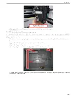
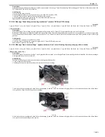
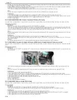
F-15-51
5. After re-installing all the relevant cartridges, turn the main power switch ON, and then check to make sure that the message is no longer displayed.
15.3.3.4.5 Multiple drum cartridges cause message "Insert drum cartridge.": Drum ITB motor (M1) is faulty
0018-3352
Color iR C3380G / Color iR C2880G / Color iR C3380i / Color iR C3380 / Color iR C2880i / Color iR C2880 / iR C3480 / iR C3480i / iR C3080i / iR C2550
[ Inspected by Canon Inc. ]
Description
Since multiple drum cartridges caused the message "Insert drum cartridge." although all the drum cartridges were mounted, the drum ITB motor (M1) was
replaced with a new one for solution.
Cause
Since the drum/ITB motor (M1) was faulty, it failed to drive drum cartridges, causing the symptom.
Field Remedy
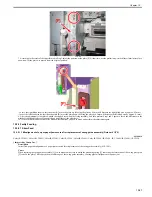
1. In service mode > COPIER > Function > PART-CHK > MTR, enter '1' using the numeric key.
2. Press [OK] and [MTR-ON] in this order, and then check to make sure that the drum ITB motor (M1) operates. (Listen to the operating noise of the motor.)
Note: Be careful. The motor may not rotate even when the indication [OK] is displayed on the LCD.
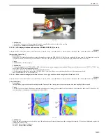
3. If the drum ITB motor (M1) does not rotate, re-fit J11051 and J1107 connector of the drum ITB motor and J210 and J209 connectors on the DC controller
PCB.
4. If the symptom still occurs, replace the drum ITB motor with a new one.
FK2-2066 DC Motor
15.3.3.4.6 Message "Insert drum cartridge." is displayed: Image formation high-voltage PCB (HV1) is faulty
0018-4040
Color iR C3380G / Color iR C2880G / Color iR C3380i / Color iR C3380 / Color iR C2880i / Color iR C2880 / iR C3480 / iR C3480i / iR C3080i / iR C2550
[ Inspected by Canon Inc. ]
Description
Since the message "Insert drum cartridge." was displayed upon power-on, the image formation high-voltage PCB (HV1) was replaced with a new one for
solution. In this inspection case, the message was displayed with regard to cyan.
Cause
Since the image formation high-voltage PCB (HV1) was faulty, high voltage was not supplied to the drum cartridge. This made this machine fail to recognize
the drum cartridge, causing the message.
Field Remedy
1. Re-fit the drum cartridge that the message is specifying.
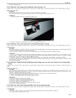
2. If the symptom still occurs, re-fit J301 and J302 connectors of the image formation high-voltage PCB (HV1) and J112A and J112B connectors of the DC
controller PCB.
3. If the symptom still occurs, replace the image formation high-voltage PCB (HV1) with a new one.
FM2-5548 Bias High Voltage PCB Assembly
15.3.3.4.7 Message "Replace the drum cartridge." appears (for all the 4 colors): Image formation high-voltage (HV1) PCB
0018-6726
Color iR C3380G / Color iR C2880G / Color iR C3380i / Color iR C3380 / Color iR C2880i / Color iR C2880 / iR C3480 / iR C3480i / iR C3080 / iR C3080i / iR
C2550
[ Inspected by Canon Inc. ]
Description
Since the message "Replace the drum cartridge." appeared (for all the 4 colors) although no drum cartridge reached the end of service life, the image formation
high-voltage PCB was replaced for solution. When the same symptom occurs, perform the following steps in sequence.
Cause
Since the image formation high-voltage (HV1) PCB was faulty, bias was not applied to the developing cylinder in each drum cartridge, causing the cylinders
to fail to attract toner particles. This machine recognized this situation as a fault in each drum cartridge, and displayed the message.
Field Remedy
1. Pull out the drum cartridges and then re-insert them.
2. Re-fit all the connectors of the image formation high-voltage (HV1) PCB.
3. Re-fit J112A and J112B connectors of the DC controller PCB.
4. Replace the image formation high-voltage (HV1) PCB with a new one.
FM2-5548 Bias High Voltage PCB Assembly
15.3.3.4.8 Message "Insert the drum cartridge." appears (for all the 4 colors): Image formation high-voltage (HV1) PCB
0018-6727
Color iR C3380G / Color iR C2880G / Color iR C3380i / Color iR C3380 / Color iR C2880i / Color iR C2880 / iR C3480 / iR C3480i / iR C3080 / iR C3080i / iR
C2550
Summary of Contents for CiRC2550
Page 2: ......
Page 27: ...Chapter 1 Introduction ...
Page 28: ......
Page 47: ...Chapter 1 1 18 F 1 14 ON OFF ON OFF ...
Page 70: ...Chapter 1 1 41 5 Turn on the main power switch ...
Page 79: ...Chapter 2 Installation ...
Page 80: ......
Page 85: ...Chapter 2 2 3 Not available in some regions ...
Page 134: ...Chapter 3 Basic Operation ...
Page 135: ......
Page 137: ......
Page 143: ...Chapter 4 Main Controller ...
Page 144: ......
Page 152: ...Chapter 4 4 6 F 4 6 CPU HDD ROM access to the program at time of execution ...
Page 171: ...Chapter 5 Original Exposure System ...
Page 172: ......
Page 203: ...Chapter 6 Laser Exposure ...
Page 204: ......
Page 206: ......
Page 220: ...Chapter 7 Image Formation ...
Page 221: ......
Page 277: ...Chapter 8 Pickup Feeding System ...
Page 278: ......
Page 282: ......
Page 336: ...Chapter 9 Fixing System ...
Page 337: ......
Page 339: ......
Page 357: ...Chapter 10 Externals and Controls ...
Page 358: ......
Page 362: ......
Page 366: ...Chapter 10 10 4 F 10 2 F 10 3 FM1 FM2 FM5 FM8 FM11 FM4 FM3 FM6 FM7 FM9 FM10 ...
Page 375: ...Chapter 10 10 13 F 10 10 2 Remove the check mark from SNMP Status Enabled ...
Page 376: ...Chapter 10 10 14 F 10 11 ...
Page 402: ...Chapter 11 MEAP ...
Page 403: ......
Page 405: ......
Page 452: ...Chapter 12 RDS ...
Page 453: ......
Page 455: ......
Page 464: ...Chapter 13 Maintenance and Inspection ...
Page 465: ......
Page 467: ......
Page 469: ...Chapter 13 13 2 F 13 1 8 9 1 2 3 3 5 6 7 10 11 12 13 14 4 ...
Page 474: ...Chapter 14 Standards and Adjustments ...
Page 475: ......
Page 477: ......
Page 485: ......
Page 486: ...Chapter 15 Correcting Faulty Images ...
Page 487: ......
Page 495: ...Chapter 15 15 4 F 15 2 COLOR M 1 COLOR Y C K 0 ...
Page 569: ...Chapter 15 15 78 F 15 82 J102 J107 J103 J108 J101 J109 J106 J112 J115 J113 J114 J104 J105 ...
Page 570: ...Chapter 16 Self Diagnosis ...
Page 571: ......
Page 573: ......
Page 600: ...Chapter 17 Service Mode ...
Page 601: ......
Page 603: ......
Page 712: ...Chapter 18 Upgrading ...
Page 713: ......
Page 715: ......
Page 746: ...Chapter 19 Service Tools ...
Page 747: ......
Page 749: ......
Page 752: ...APPENDIX ...
Page 774: ......


