


Chapter 17
17-39
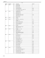
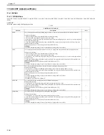
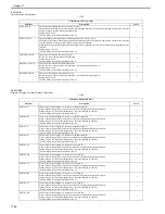
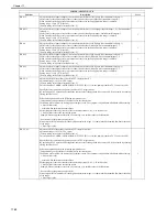
5. DENS
Concentration of developer in developer unit.
T-17-29
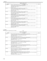
REG-HS-C
Finely adjust the writing position (in the main scanning direction) of the pattern for C
Offset the writing position of C-color images (in the main scanning direction) in the unit of 1/16 pixel. Use this item to
adjust color misalignment in the main scanning direction in the unit of 1/16 pixel.
Setting range: -128 to 127
[Factory setting value/Value after RAM clear: 0]
1
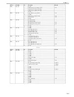
REG-HS-K
Finely adjust the writing position (in the main scanning direction) of the pattern for K
Offset the writing position of K-color images (in the main scanning direction) in the unit of 1/16 pixel. Use this item to
adjust color misalignment in the main scanning direction in the unit of 1/16 pixel.
Setting range: -128 to 127
[Factory setting value/Value after RAM clear: 0]
1
REG-V-Y
Coarsely adjust the writing position (in the sub scanning direction) of the pattern for Y
Offset the writing position of Y-color images (in the sub scanning direction) in the unit of pixel. Use this item to adjust
color misalignment in the sub scanning direction in the unit of pixel.
Setting range: -128 to 127
[Factory setting value/Value after RAM clear: 0]
1
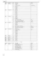
REG-V-M
Coarsely adjust the writing position (in the sub scanning direction) of the pattern for M
Offset the writing position of M-color images (in the sub scanning direction) in the unit of pixel. Use this item to adjust
color misalignment in the sub scanning direction in the unit of pixel.
Setting range: -128 to 127
[Factory setting value/Value after RAM clear: 0]
1
REG-V-C
Coarsely adjust the writing position (in the sub scanning direction) of the pattern for C
Offset the writing position of C-color images (in the sub scanning direction) in the unit of pixel. Use this item to adjust
color misalignment in the sub scanning direction in the unit of pixel.
Setting range: -128 to 127
[Factory setting value/Value after RAM clear: 0]
1
REG-V-K
Coarsely adjust the writing position (in the sub scanning direction) of the pattern for K
Offset the writing position of K-color images (in the sub scanning direction) in the unit of pixel. Use this item to adjust
color misalignment in the sub scanning direction in the unit of pixel.
Setting range: -128 to 127
[Factory setting value/Value after RAM clear: 0]
1
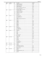
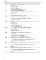
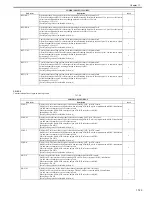
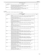
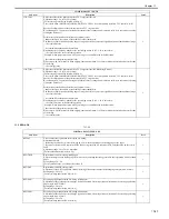
COPIER>ADJUST>DENS
Sub item
Description
level.
SGNL-Y
Display the Y-color toner density signal value when executing "INIT" for ATR control.
Display the Y-color toner density signal value when executing ATR-INIT, which is implemented at PCRG initialization.
Use this item to determine a cause of a density fault.
When replacing the DCON PCB, enter the unique ATR-INIT value for each PCRG.
Setting range: 0 to 65535
[Factory setting value/Value after RAM clear: 0]
1
SGNL-M
Display the M-color toner density signal value when executing "INIT" for ATR control.
Display the M-color toner density signal value when executing ATR-INIT, which is implemented at PCRG initialization.
Use this item to determine a cause of a density fault.
When replacing the DCON PCB, enter the unique ATR-INIT value for each PCRG.
Setting range: 0 to 65535
[Factory setting value/Value after RAM clear: 0]
1
SGNL-C
Display the C-color toner density signal value when executing "INIT" for ATR control.
Display the C-color toner density signal value when executing ATR-INIT, which is implemented at PCRG initialization.
Use this item to determine a cause of a density fault.
When replacing the DCON PCB, enter the unique ATR-INIT value for each PCRG.
Setting range: 0 to 65535
[Factory setting value/Value after RAM clear: 0]
1
SGNL-K
Display the K-color toner density signal value when executing "INIT" for ATR control.
Display the K-color toner density signal value when executing ATR-INIT, which is implemented at PCRG initialization.
Use this item to determine a cause of a density fault.
When replacing the DCON PCB, enter the unique ATR-INIT value for each PCRG.
Setting range: 0 to 65535
[Factory setting value/Value after RAM clear: 0]
1
SIGG-Y
Display the gain value for the Y-color toner density standard signal for ATR control.
Display the Y-color patch level when executing ATR-INIT, which is executed at PCRG initialization.
Use this item to determine a cause of a density fault.
When replacing the DCON PCB, enter the unique ATR-INIT value for each PCRG.
Setting range: 0 to 255
[Factory setting value/Value after RAM clear: 0]
1
SIGG-M
Display the gain value for the M-color toner density standard signal for ATR control.
Display the M-color patch level when executing ATR-INIT, which is executed at PCRG initialization.
Use this item to determine a cause of a density fault.
When replacing the DCON PCB, enter the unique ATR-INIT value for each PCRG.
Setting range: 0 to 255
[Factory setting value/Value after RAM clear: 0]
1
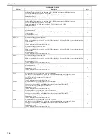
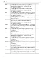
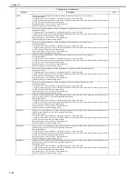
COPIER>ADJUST>IMG-REG
Sub item
Description
level.
Summary of Contents for CiRC2550
Page 2: ......
Page 27: ...Chapter 1 Introduction ...
Page 28: ......
Page 47: ...Chapter 1 1 18 F 1 14 ON OFF ON OFF ...
Page 70: ...Chapter 1 1 41 5 Turn on the main power switch ...
Page 79: ...Chapter 2 Installation ...
Page 80: ......
Page 85: ...Chapter 2 2 3 Not available in some regions ...
Page 134: ...Chapter 3 Basic Operation ...
Page 135: ......
Page 137: ......
Page 143: ...Chapter 4 Main Controller ...
Page 144: ......
Page 152: ...Chapter 4 4 6 F 4 6 CPU HDD ROM access to the program at time of execution ...
Page 171: ...Chapter 5 Original Exposure System ...
Page 172: ......
Page 203: ...Chapter 6 Laser Exposure ...
Page 204: ......
Page 206: ......
Page 220: ...Chapter 7 Image Formation ...
Page 221: ......
Page 277: ...Chapter 8 Pickup Feeding System ...
Page 278: ......
Page 282: ......
Page 336: ...Chapter 9 Fixing System ...
Page 337: ......
Page 339: ......
Page 357: ...Chapter 10 Externals and Controls ...
Page 358: ......
Page 362: ......
Page 366: ...Chapter 10 10 4 F 10 2 F 10 3 FM1 FM2 FM5 FM8 FM11 FM4 FM3 FM6 FM7 FM9 FM10 ...
Page 375: ...Chapter 10 10 13 F 10 10 2 Remove the check mark from SNMP Status Enabled ...
Page 376: ...Chapter 10 10 14 F 10 11 ...
Page 402: ...Chapter 11 MEAP ...
Page 403: ......
Page 405: ......
Page 452: ...Chapter 12 RDS ...
Page 453: ......
Page 455: ......
Page 464: ...Chapter 13 Maintenance and Inspection ...
Page 465: ......
Page 467: ......
Page 469: ...Chapter 13 13 2 F 13 1 8 9 1 2 3 3 5 6 7 10 11 12 13 14 4 ...
Page 474: ...Chapter 14 Standards and Adjustments ...
Page 475: ......
Page 477: ......
Page 485: ......
Page 486: ...Chapter 15 Correcting Faulty Images ...
Page 487: ......
Page 495: ...Chapter 15 15 4 F 15 2 COLOR M 1 COLOR Y C K 0 ...
Page 569: ...Chapter 15 15 78 F 15 82 J102 J107 J103 J108 J101 J109 J106 J112 J115 J113 J114 J104 J105 ...
Page 570: ...Chapter 16 Self Diagnosis ...
Page 571: ......
Page 573: ......
Page 600: ...Chapter 17 Service Mode ...
Page 601: ......
Page 603: ......
Page 712: ...Chapter 18 Upgrading ...
Page 713: ......
Page 715: ......
Page 746: ...Chapter 19 Service Tools ...
Page 747: ......
Page 749: ......
Page 752: ...APPENDIX ...
Page 774: ......


