


Chapter 15
15-47
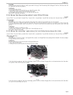
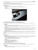
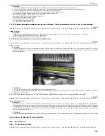
15.3.7.9 E020-0200: Connector at Process unit has poor contact
0018-1364
Color iR C3380G / Color iR C2880G / Color iR C3380i / Color iR C3380 / Color iR C2880i / Color iR C2880 / iR C3480 / iR C3480i / iR C3080i / iR C2550
[ Inspected by Canon Inc. ]
Description
Since the error code "E020-0200" occurred, J1175 connector of the process unit was disconnected and then re-connected for solution.
- E020-020x error code can be displayed when the patch level of each color is lower than the lower limit at the time of ATR initialization. (0200: yellow,
0201: magenta, 0202: cyan, and 0203: black)
Cause
J1175 connector of the process unit had poor contact, the information of the patch detection sensor was not sent to the DC driver PCB, causing E020-0200
error.
Field Remedy
1. Re-fit J221 connector of the DC driver PCB.
2. Re-fit J1175 and J1235 connectors of the process unit.
3. Re-fit J1155 connector of the patch detection sensor.
4. If the symptom still occurs, replace the patch detection sensor (UN18) with a new one.
RH7-7129 OHT Sensor Unit
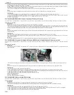
15.3.7.10 E025-0003: Toner rotation volume sensor (PS6) is soiled
0018-0425
Color iR C3380G / Color iR C2880G / Color iR C3380i / Color iR C3380 / Color iR C2880i / Color iR C2880 / iR C3480 / iR C3480i / iR C3080i / iR C2550
[ Inspected by Canon Inc. ]
Description
Since the error code "E025-0003" was displayed, the toner rotation volume sensor (PS6) was cleaned for solution.
- E025-0003 can be displayed when an error of Bk developing assembly toner supply occurs.
Cause
Since the toner cartridge installation was performed repeatedly, cyan toner fell from the gear in the front side and accumulated on the toner rotation volume
sensor (PS6).
Field Remedy
1. Check if the toner rotation volume sensor (PS6) is soiled with toner; if so, clean the sensor.
2. If the symptom still occurs, re-fit J2005 and J2007 connectors of the DC controller PCB.
3. If the symptom still occurs, replace the DC controller PCB with a new one.
FM2-8263 DC Controller PCB Assembly
15.3.7.11 E025: Connector of process kit relay PCB has poor contact
0018-6729
Color iR C3380G / Color iR C2880G / Color iR C3380i / Color iR C3380 / Color iR C2880i / Color iR C2880 / iR C3480 / iR C3480i / iR C3080 / iR C3080i / iR
C2550
[ Inspected by Canon Inc. ]
Description
Since the error code "E025" was displayed, all the connectors of the process kit reply PCB were disconnected and then re-connected for solution.
- E025 can be displayed when the toner motor error occurs.
Cause
Since J552 connector of the process kit reply PCB had poor contact, the toner motor malfunctioned, causing E025 error.
Field Remedy
1. Re-fit all the connectors of the process kit reply PCB.
2. Re-fit J2005, J2008, J2010, and J2012 connectors of the DC controller PCB.
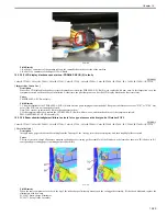
15.3.7.12 E045 is displayed during startup after power-on: OHT sensor unit is faulty
0016-1366
Color iR C3380G / Color iR C2880G / Color iR C3380i / Color iR C3380 / Color iR C2880i / Color iR C2880 / iR C3480 / iR C3480i / iR C3080i / iR C2550
[ Case in the field ]
Description
Since this machine indicated the error code "E045" during startup (i.e., when the progress bar reached the point of two-thirds of its whole way) after power-
on, the OHT sensor unit was replaced with a new one for solution.
- E045 can be displayed when an OHT sensor error occurs.
Field Remedy
1. Re-fit the connectors at J212 and J221 on the DC Driver PCB.
2. If the symptom still occurs, check if the OHT sensor unit is mounted correctly.
3. If the sensor unit is mounted correctly, replace the OHT sensor unit with a new one.
RH7-7129 OHT Sensor Unit
15.3.7.13 E067-0102: DC Controller PCB has poor contact
0016-3015
Color iR C3380G / Color iR C2880G / Color iR C3380i / Color iR C3380 / Color iR C2880i / Color iR C2880 / iR C3480 / iR C3480i / iR C3080i / iR C2550
[ Inspected by Canon Inc. ]
Description
Since the error code "E067-0102" was indicated, all the connectors of the DC Controller PCB were re-fit for solution.
- E067-0102 can be displayed when the two detected currents of primary transfer ATVC are both the threshold or less.
Field Remedy
1. Check to see if the primary transfer roller spring is deformed or detached.
2. Clean the point of contact of the primary transfer roller.
3. Make the following selections in sequence [Service mode > COPIER > Display > MISC > DRM-LIFE] to check the setting value; if the value is around
'100', suspect that the drum almost reaches the end of life, and replace the drum unit with a new one.
4. If the symptom still occurs, re-fit all the connectors of the DC Controller PCB.
5. If Step 4 does not work on the symptom, output P-Print printouts, and then replace the DC Controller PCB with a new one.
Service mode > COPIER > Function > MISC-P > P-PRINT
Summary of Contents for CiRC2550
Page 2: ......
Page 27: ...Chapter 1 Introduction ...
Page 28: ......
Page 47: ...Chapter 1 1 18 F 1 14 ON OFF ON OFF ...
Page 70: ...Chapter 1 1 41 5 Turn on the main power switch ...
Page 79: ...Chapter 2 Installation ...
Page 80: ......
Page 85: ...Chapter 2 2 3 Not available in some regions ...
Page 134: ...Chapter 3 Basic Operation ...
Page 135: ......
Page 137: ......
Page 143: ...Chapter 4 Main Controller ...
Page 144: ......
Page 152: ...Chapter 4 4 6 F 4 6 CPU HDD ROM access to the program at time of execution ...
Page 171: ...Chapter 5 Original Exposure System ...
Page 172: ......
Page 203: ...Chapter 6 Laser Exposure ...
Page 204: ......
Page 206: ......
Page 220: ...Chapter 7 Image Formation ...
Page 221: ......
Page 277: ...Chapter 8 Pickup Feeding System ...
Page 278: ......
Page 282: ......
Page 336: ...Chapter 9 Fixing System ...
Page 337: ......
Page 339: ......
Page 357: ...Chapter 10 Externals and Controls ...
Page 358: ......
Page 362: ......
Page 366: ...Chapter 10 10 4 F 10 2 F 10 3 FM1 FM2 FM5 FM8 FM11 FM4 FM3 FM6 FM7 FM9 FM10 ...
Page 375: ...Chapter 10 10 13 F 10 10 2 Remove the check mark from SNMP Status Enabled ...
Page 376: ...Chapter 10 10 14 F 10 11 ...
Page 402: ...Chapter 11 MEAP ...
Page 403: ......
Page 405: ......
Page 452: ...Chapter 12 RDS ...
Page 453: ......
Page 455: ......
Page 464: ...Chapter 13 Maintenance and Inspection ...
Page 465: ......
Page 467: ......
Page 469: ...Chapter 13 13 2 F 13 1 8 9 1 2 3 3 5 6 7 10 11 12 13 14 4 ...
Page 474: ...Chapter 14 Standards and Adjustments ...
Page 475: ......
Page 477: ......
Page 485: ......
Page 486: ...Chapter 15 Correcting Faulty Images ...
Page 487: ......
Page 495: ...Chapter 15 15 4 F 15 2 COLOR M 1 COLOR Y C K 0 ...
Page 569: ...Chapter 15 15 78 F 15 82 J102 J107 J103 J108 J101 J109 J106 J112 J115 J113 J114 J104 J105 ...
Page 570: ...Chapter 16 Self Diagnosis ...
Page 571: ......
Page 573: ......
Page 600: ...Chapter 17 Service Mode ...
Page 601: ......
Page 603: ......
Page 712: ...Chapter 18 Upgrading ...
Page 713: ......
Page 715: ......
Page 746: ...Chapter 19 Service Tools ...
Page 747: ......
Page 749: ......
Page 752: ...APPENDIX ...
Page 774: ......