

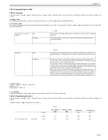


Chapter 10
10-23
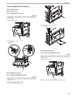
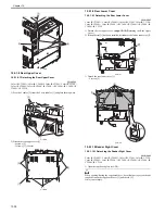
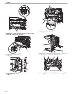
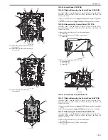
F-10-52
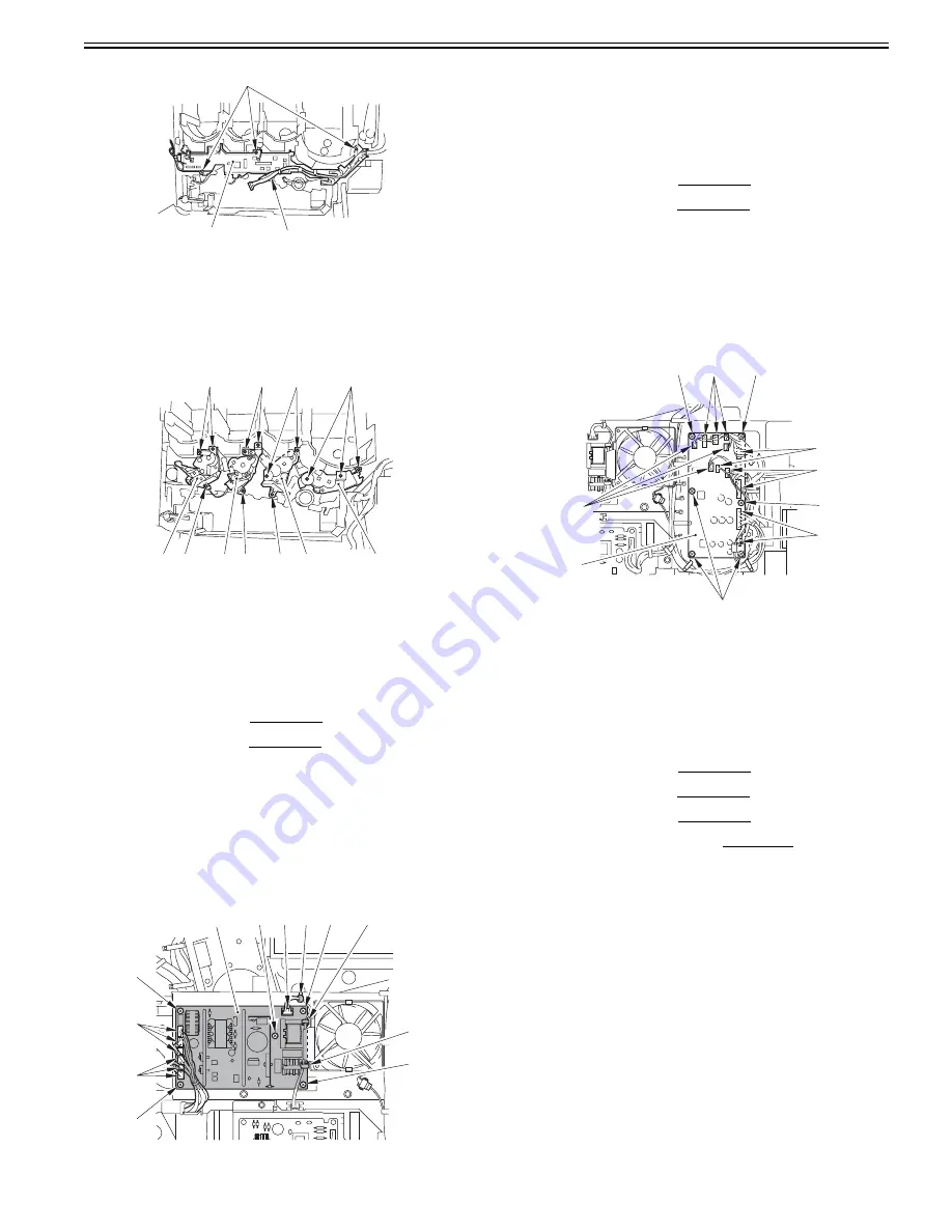
11) Remove the hopper drive unit (Y) [1].
- 3 screws [2]
12) Remove the hopper drive unit (M) [3].
- 3 screws [4]
13) Remove the hopper drive unit (C) [5].
- 3 screws [6]
14) Remove the hopper drive unit (Bk) [7].
- 3 screws [8]
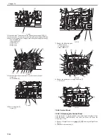
F-10-53
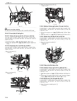
10.5.3 Option Power Supply Assembly
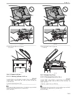
10.5.3.1 Before Detaching the Optional Power Supply
PCB
0014-2578
Color iR C3380G / Color iR C2880G / Color iR C3380i / Color iR C3380 /
Color iR C2880i / Color iR C2880 / iR C3480 / iR C3480i / iR C3080 / iR
C3080i / iR C2550
1) Detach the rear upper cover.
[Detaching the Rear Upper
Cover]
2) Detach the rear lower cover.
[Detaching the Rear Lower
Cover]
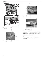
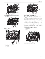
10.5.3.2 Detaching the Optional Power Supply PCB
0014-2579
Color iR C3380G / Color iR C2880G / Color iR C3380i / Color iR C3380 /
Color iR C2880i / Color iR C2880 / iR C3480 / iR C3480i / iR C3080 / iR
C3080i / iR C2550
1) Detach the optional power supply PCB [1].
- 7 connectors [2]
- 3 wire saddles [3]
- 5 screws [4]
F-10-54
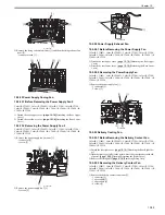
10.5.4 Controller Power Supply Unit
10.5.4.1 Before Detaching the Controller Power Supply
PCB
0013-6816
Color iR C3380G / Color iR C2880G / Color iR C3380i / Color iR C3380 /
Color iR C2880i / Color iR C2880 / iR C3480 / iR C3480i / iR C3080 / iR
C3080i / iR C2550
1) Detach the rear upper cover.
[Detaching the Rear Upper
Cover]
2) Detach the rear lower cover.
[Detaching the Rear Lower
Cover]
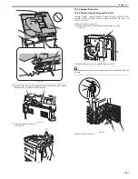
10.5.4.2 Detaching the Controller Power Supply PCB
0013-6817
Color iR C3380G / Color iR C2880G / Color iR C3380i / Color iR C3380 /
Color iR C2880i / Color iR C2880 / iR C3480 / iR C3480i / iR C3080 / iR
C3080i / iR C2550
1) Detach the controller power supply PCB [1].
- 12 connectors [2]
- 6 screws [3]
F-10-55
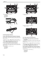
10.5.5 Printer Power Supply Unit
10.5.5.1 Before Detaching the Printer Power Supply
Assembly
0014-2490
Color iR C3380G / Color iR C2880G / Color iR C3380i / Color iR C3380 /
Color iR C2880i / Color iR C2880 / iR C3480 / iR C3480i / iR C3080 / iR
C3080i / iR C2550
1) Detach the rear upper cover.
[Detaching the Rear Upper
Cover]
2) Detach the rear lower cover.
[Detaching the Rear Lower
Cover]
3) Detach the left lower cover.
[Detaching the Left Lower
Cover]
4) Detach the all-night power supply PCB.
[Detaching the All-
Night Power Supply PCB]
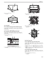
10.5.5.2 Detaching the Printer Power Supply Assembly
0014-2491
Color iR C3380G / Color iR C2880G / Color iR C3380i / Color iR C3380 /
Color iR C2880i / Color iR C2880 / iR C3480 / iR C3480i / iR C3080 / iR
C3080i / iR C2550
1) Remove the power supply fan 2 mount [1].
- 1 connector [2]
- 1 screw [3]
[1]
[2]
[3]
[2]
[4]
[6]
[8]
[7]
[1]
[3]
[2]
[4]
[6]
[5]
[1]
[2]
[4]
[4]
[3]
[4]
[2]
[4] [2] [3]
[4]
[3]
[2]
[2]
[2]
[2]
[3]
[2]
[3]
[3]
[3]
[1]
Summary of Contents for CiRC2550
Page 2: ......
Page 27: ...Chapter 1 Introduction ...
Page 28: ......
Page 47: ...Chapter 1 1 18 F 1 14 ON OFF ON OFF ...
Page 70: ...Chapter 1 1 41 5 Turn on the main power switch ...
Page 79: ...Chapter 2 Installation ...
Page 80: ......
Page 85: ...Chapter 2 2 3 Not available in some regions ...
Page 134: ...Chapter 3 Basic Operation ...
Page 135: ......
Page 137: ......
Page 143: ...Chapter 4 Main Controller ...
Page 144: ......
Page 152: ...Chapter 4 4 6 F 4 6 CPU HDD ROM access to the program at time of execution ...
Page 171: ...Chapter 5 Original Exposure System ...
Page 172: ......
Page 203: ...Chapter 6 Laser Exposure ...
Page 204: ......
Page 206: ......
Page 220: ...Chapter 7 Image Formation ...
Page 221: ......
Page 277: ...Chapter 8 Pickup Feeding System ...
Page 278: ......
Page 282: ......
Page 336: ...Chapter 9 Fixing System ...
Page 337: ......
Page 339: ......
Page 357: ...Chapter 10 Externals and Controls ...
Page 358: ......
Page 362: ......
Page 366: ...Chapter 10 10 4 F 10 2 F 10 3 FM1 FM2 FM5 FM8 FM11 FM4 FM3 FM6 FM7 FM9 FM10 ...
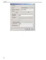
Page 375: ...Chapter 10 10 13 F 10 10 2 Remove the check mark from SNMP Status Enabled ...
Page 376: ...Chapter 10 10 14 F 10 11 ...
Page 402: ...Chapter 11 MEAP ...
Page 403: ......
Page 405: ......
Page 452: ...Chapter 12 RDS ...
Page 453: ......
Page 455: ......
Page 464: ...Chapter 13 Maintenance and Inspection ...
Page 465: ......
Page 467: ......
Page 469: ...Chapter 13 13 2 F 13 1 8 9 1 2 3 3 5 6 7 10 11 12 13 14 4 ...
Page 474: ...Chapter 14 Standards and Adjustments ...
Page 475: ......
Page 477: ......
Page 485: ......
Page 486: ...Chapter 15 Correcting Faulty Images ...
Page 487: ......
Page 495: ...Chapter 15 15 4 F 15 2 COLOR M 1 COLOR Y C K 0 ...
Page 569: ...Chapter 15 15 78 F 15 82 J102 J107 J103 J108 J101 J109 J106 J112 J115 J113 J114 J104 J105 ...
Page 570: ...Chapter 16 Self Diagnosis ...
Page 571: ......
Page 573: ......
Page 600: ...Chapter 17 Service Mode ...
Page 601: ......
Page 603: ......
Page 712: ...Chapter 18 Upgrading ...
Page 713: ......
Page 715: ......
Page 746: ...Chapter 19 Service Tools ...
Page 747: ......
Page 749: ......
Page 752: ...APPENDIX ...
Page 774: ......


