


Chapter 15
15-54
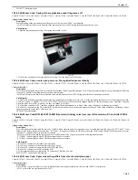
15.3.7.41 E748-4031/long start-up time and progress bar stops at point of one-twentieth although these symptoms are
temporarily solved by powering OFF/ON: Hard Disk Drive (HDD) is faulty
0016-3162
Color iR C3380G / Color iR C2880G / Color iR C3380i / Color iR C3380 / Color iR C2880i / Color iR C2880 / iR C3480 / iR C3480i / iR C3080i / iR C2550
[ Inspected by Canon Inc. ]
Description
When the error code "E748-4031" was indicated, the main power switch was turned OFF/ON. This solution temporarily worked on the error; however such
a phenomenon as the machine required a long period of time for warm-up or the progress bar stopped at the point of one-twentieth the way occurred.
Therefore, the HDD was replaced with a new one.
- E748-4031 can be displayed when a HDD access error occurs.
Field Remedy
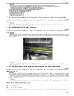
1. Check to see the adhesion condition of the aluminum tape on the HDD.
2. Re-fit the Main Controller PCB (including Sub PCBs).
3. If Step 1 and 2 do not work, re-fit all the connectors of the HDD.
4. If Step 3 does not work, replace the HDD with a new one.
5. If Step 4 does not work, re-fit the LANBER-C PCB.
6. If Step 5 does not work, replace the LANBER-C PCB with a new one.
7. If Step 6 does not work, re-fit all the connector of the Main Controller PCB.
8. If Step 7 does not work, replace the Main Controller PCB with a new one.
FM2-9163 Main Controller PCB Assembly
FM2-9165 LANBAER-C PCB Assembly
FM2-8258 HDD
15.3.7.42 E748-4000: Voltage of power supplied to this machine drops
0016-4960
Color iR C3380G / Color iR C2880G / Color iR C3380i / Color iR C3380 / Color iR C2880i / Color iR C2880 / iR C3480 / iR C3480i / iR C3080i / iR C2550
[ Inspected by Canon Inc. ]
Description
Since the outlet from which power was supplied to this machine was used as the power source for other devices, the voltage of power to this machine dropped,
causing the error code "E748-4000." In this field case, the voltage of power supplied to this 100V machine dropped less than 80V when measured with a
widely used tester.
- E748-4000 can be displayed when any ASIC of the Main Controller PCB (Sub SJ/PE/R) or ASIC of the open interface PCB is not detected.
Field Remedy
1. Check to see if the outlet supplying power to this machine is used as the power source of other device(s).
2. If the outlet is shared with other device(s), measure the power voltage supplied to this machine with a tester.
Note: Widely used testers are insensitive and sometimes show a lower voltage than the actual.
3. In case the measured voltage is without the range of -/+ 10% of the nominal-rated voltage, disconnect the power plug of the other device(s) sharing the
power source with this machine, and then check to see again if this machine indicates the error code.
Reference: The symptom is likely to occur when this machine performs the first job in the morning in a state in which it has been completely cooled during
nighttime and power voltage supplied from the outlet drops.
4. If the error code is solved, ask the user not to make this machine share the power source with other device(s).
15.3.7.43 E748-4000: Main controller PCB (main) is faulty
0018-3388
Color iR C3380G / Color iR C2880G / Color iR C3380i / Color iR C3380 / Color iR C2880i / Color iR C2880 / iR C3480 / iR C3480i / iR C3080i / iR C2550
[ Inspected by Canon Inc. ]
Description
Since the error code "E748-4000" was displayed, the main controller PCB (main) was replaced with a new one for solution.
- E748-4000 can be displayed when any ASIC of the main controller PCB (sub SJ/PE/R) is not detected.
Cause
Since the main controller PCB (main) was faulty, no ASIC was detected, causing the error code.
Field Remedy
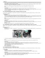
1. Re-fit each main controller PCB (sub SJ/PE/R).
2. Re-fit J1014 connector of the main controller PCB.
3. Re-fit J301 and J106 connectors of the DC controller PCB.
4. Re-fit J202, J220, and J221B connectors of the printer unit power supply PCB.
5. If the symptom still occurs, replace the main controller PCB (main) with a new one.
FM2-9163 Main Controller PCB Assembly
15.3.7.44 E748-4883: Main controller PCB (main) is faulty
0018-7043
Color iR C3380G / Color iR C2880G / Color iR C3380i / Color iR C3380 / Color iR C2880i / Color iR C2880 / iR C3480 / iR C3480i / iR C3080 / iR C3080i / iR
C2550
[ Inspected by Canon Inc. ]
Description
Since this machine stopped the progress bar at a point of 5mm upon power-on and, then, indicated the error code "E748-4883" a little while later, the main
controller PCB (main) was replaced with a new one for solution.
- E748-4883 can be displayed when CPU causes a bus lock at initialization of main controller PCB (sub RB-A) during start-up.
Field Remedy
1. Re-fit the main controller PCB (sub RB-A).
2. If the symptom still occurs, replace the main controller PCB (sub RB-A) with a new one.
3. If the symptom still occurs, replace the main controller PCB (main) with a new one.
FM2-9161 RB-A2 PCB Assembly
FM2-9163 Main Controller PCB Assembly
15.3.7.45 E749-0001/E749-0003: Instruction to restart accompanying change in product configuration
0015-8321
Color iR C3380G / Color iR C2880G / Color iR C3380i / Color iR C3380 / Color iR C2880i / Color iR C2880 / iR C3480 / iR C3480i / iR C3080i / iR C2550
[ Manual-related ]
Description
Summary of Contents for CiRC2550
Page 2: ......
Page 27: ...Chapter 1 Introduction ...
Page 28: ......
Page 47: ...Chapter 1 1 18 F 1 14 ON OFF ON OFF ...
Page 70: ...Chapter 1 1 41 5 Turn on the main power switch ...
Page 79: ...Chapter 2 Installation ...
Page 80: ......
Page 85: ...Chapter 2 2 3 Not available in some regions ...
Page 134: ...Chapter 3 Basic Operation ...
Page 135: ......
Page 137: ......
Page 143: ...Chapter 4 Main Controller ...
Page 144: ......
Page 152: ...Chapter 4 4 6 F 4 6 CPU HDD ROM access to the program at time of execution ...
Page 171: ...Chapter 5 Original Exposure System ...
Page 172: ......
Page 203: ...Chapter 6 Laser Exposure ...
Page 204: ......
Page 206: ......
Page 220: ...Chapter 7 Image Formation ...
Page 221: ......
Page 277: ...Chapter 8 Pickup Feeding System ...
Page 278: ......
Page 282: ......
Page 336: ...Chapter 9 Fixing System ...
Page 337: ......
Page 339: ......
Page 357: ...Chapter 10 Externals and Controls ...
Page 358: ......
Page 362: ......
Page 366: ...Chapter 10 10 4 F 10 2 F 10 3 FM1 FM2 FM5 FM8 FM11 FM4 FM3 FM6 FM7 FM9 FM10 ...
Page 375: ...Chapter 10 10 13 F 10 10 2 Remove the check mark from SNMP Status Enabled ...
Page 376: ...Chapter 10 10 14 F 10 11 ...
Page 402: ...Chapter 11 MEAP ...
Page 403: ......
Page 405: ......
Page 452: ...Chapter 12 RDS ...
Page 453: ......
Page 455: ......
Page 464: ...Chapter 13 Maintenance and Inspection ...
Page 465: ......
Page 467: ......
Page 469: ...Chapter 13 13 2 F 13 1 8 9 1 2 3 3 5 6 7 10 11 12 13 14 4 ...
Page 474: ...Chapter 14 Standards and Adjustments ...
Page 475: ......
Page 477: ......
Page 485: ......
Page 486: ...Chapter 15 Correcting Faulty Images ...
Page 487: ......
Page 495: ...Chapter 15 15 4 F 15 2 COLOR M 1 COLOR Y C K 0 ...
Page 569: ...Chapter 15 15 78 F 15 82 J102 J107 J103 J108 J101 J109 J106 J112 J115 J113 J114 J104 J105 ...
Page 570: ...Chapter 16 Self Diagnosis ...
Page 571: ......
Page 573: ......
Page 600: ...Chapter 17 Service Mode ...
Page 601: ......
Page 603: ......
Page 712: ...Chapter 18 Upgrading ...
Page 713: ......
Page 715: ......
Page 746: ...Chapter 19 Service Tools ...
Page 747: ......
Page 749: ......
Page 752: ...APPENDIX ...
Page 774: ......


