


Chapter 17
17-92
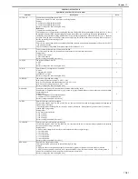
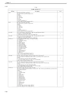
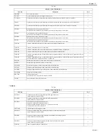
5. INT-FACE
MIC-TUN
Manual tuning of microphone used for voice recognition
This allows the audio intake level sensitivity to be adjusted manually for the input device connected by the user. This
item is operated and the adjustment made if the sensitivity of the microphone is not increased enough with automatic
tuning.
Reference:
See below for automatic tuning.
Initial settings/registration > system control > voice control settings > microphone tuning
Setting range: 0 to 255
[Factory setting/value after clearing RAM: 128]
1
SRL-SPSW
Support level setting of serial I/F for account management
Use this when supporting the serial I/F (remote counter supporting serial communication) for account management.
If it is supported, the setting can be changed according to the printing cancel condition when the host machine receives
Disable signal (no copy).
In setting 1, extra printout will be made compared to setting 2 because this setting gives priority to printing speed.
Settings
0: Does not support
1: Supported (speed-priority)
2: Supported (stop-priority)
MEMO:
- Reference function: COPIER > OPTION > ACC > CC-SPSW
[Factory settings/setting values after RAM clear: 0]
1
CC-EXT
Port output setting for additional information of control card I/F
When installing the control card I/F, specify whether to output the additional information (large/small information and
color/mono information) from iR machine to account device.
However, to output this additional information, port connecting kit-A1 is required.
Setting values
0: Does not output
1: Output
[Factory settings/setting values after RAM clear: 0]
1
STPL-LMT *1
Used to restrict number of sheets for saddle binding.
0: 5 sheets (no white band)
1: 10 sheets (no white band)
2: 10 sheets (white band)
3: 15 sheets (no white band) [Factory default/After RAM clear]
2
SC-TYPE
Used to switch type of coin vendor-compatible model
Whenever possible, avoid using this setting during normal operation.
2
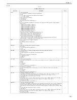
CC-SPSW
use it to enable/disable support of the switch in relation to the support level of the control guard I/F
0: do not support [Factory default/After RAM clear]
1: support (priority on speed)
2: support (priority on upper limit on number of prints)
Reference:
negative effects of '1'
- the machine may fail to use an accurate stop based on the upper limit
negative effects of '2'
- some source of power (pickup assembly) may suffer a drop in productivity
2
UNIT-PRC
Setting of unit prices handled by coin vendor
Settings
0: Japanese yen
1: Euros
2: Pounds
3: Swiss francs
4: Dollars
5: No unit, no fractional monetary unit provided
6: No unit, fractional monetary unit provided
[Factory setting/value after clearing RAM: 0]
2
DA-PUCT
Sheet feed/delivery communication setting with DA charges
This mode prevents the kind of trouble where iR continues to output the sheet feed notification and prints continue to be
made free of charge even when there is something wrong with the sheet feed/delivery notification because of trouble in
the network.
No sheets are fed if the difference between the number of times iR has given sheet feed notification and the number of
sheets for which sheet feed acknowledge is returned from DA during sheet feed/delivery communication between iR and
DA is higher than this item's setting. If this item is set too low, a poor engine performance results which is a
disadvantage.
Setting range: 2 to 10
[Factory setting/value after clearing RAM: 6]
2
COPIER>OPTION>ACC
Sub item
Description
level.
Summary of Contents for CiRC2550
Page 2: ......
Page 27: ...Chapter 1 Introduction ...
Page 28: ......
Page 47: ...Chapter 1 1 18 F 1 14 ON OFF ON OFF ...
Page 70: ...Chapter 1 1 41 5 Turn on the main power switch ...
Page 79: ...Chapter 2 Installation ...
Page 80: ......
Page 85: ...Chapter 2 2 3 Not available in some regions ...
Page 134: ...Chapter 3 Basic Operation ...
Page 135: ......
Page 137: ......
Page 143: ...Chapter 4 Main Controller ...
Page 144: ......
Page 152: ...Chapter 4 4 6 F 4 6 CPU HDD ROM access to the program at time of execution ...
Page 171: ...Chapter 5 Original Exposure System ...
Page 172: ......
Page 203: ...Chapter 6 Laser Exposure ...
Page 204: ......
Page 206: ......
Page 220: ...Chapter 7 Image Formation ...
Page 221: ......
Page 277: ...Chapter 8 Pickup Feeding System ...
Page 278: ......
Page 282: ......
Page 336: ...Chapter 9 Fixing System ...
Page 337: ......
Page 339: ......
Page 357: ...Chapter 10 Externals and Controls ...
Page 358: ......
Page 362: ......
Page 366: ...Chapter 10 10 4 F 10 2 F 10 3 FM1 FM2 FM5 FM8 FM11 FM4 FM3 FM6 FM7 FM9 FM10 ...
Page 375: ...Chapter 10 10 13 F 10 10 2 Remove the check mark from SNMP Status Enabled ...
Page 376: ...Chapter 10 10 14 F 10 11 ...
Page 402: ...Chapter 11 MEAP ...
Page 403: ......
Page 405: ......
Page 452: ...Chapter 12 RDS ...
Page 453: ......
Page 455: ......
Page 464: ...Chapter 13 Maintenance and Inspection ...
Page 465: ......
Page 467: ......
Page 469: ...Chapter 13 13 2 F 13 1 8 9 1 2 3 3 5 6 7 10 11 12 13 14 4 ...
Page 474: ...Chapter 14 Standards and Adjustments ...
Page 475: ......
Page 477: ......
Page 485: ......
Page 486: ...Chapter 15 Correcting Faulty Images ...
Page 487: ......
Page 495: ...Chapter 15 15 4 F 15 2 COLOR M 1 COLOR Y C K 0 ...
Page 569: ...Chapter 15 15 78 F 15 82 J102 J107 J103 J108 J101 J109 J106 J112 J115 J113 J114 J104 J105 ...
Page 570: ...Chapter 16 Self Diagnosis ...
Page 571: ......
Page 573: ......
Page 600: ...Chapter 17 Service Mode ...
Page 601: ......
Page 603: ......
Page 712: ...Chapter 18 Upgrading ...
Page 713: ......
Page 715: ......
Page 746: ...Chapter 19 Service Tools ...
Page 747: ......
Page 749: ......
Page 752: ...APPENDIX ...
Page 774: ......


