


Chapter 7
7-47
Do not touch the ITB. If the ITB is scratched, it may cause the pickup fault
or degradation of the print quality.
In case the print quality is degraded due to touching the ITB, clean the ITB
with soft and dry cloth.
If the print quality is not improved, execute the following:
[Additional Functions] > [Adjustment/Cleaning] > [Cleaning inside Main
Unit] > [Start]
F-7-64
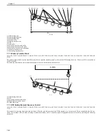
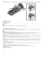
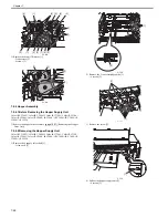
7) Secure the ITB unit [1] in place with the tip-resistant arm [2] (secure in
the lower slot of the 2).
F-7-65
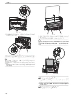
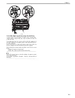
Points to note when closing the ITB unit
When closing the ITB unit [1], be sure to remove the tip-resistant arm [2]. If
closing the ITB unit with the tip-resistant arm fixed, the tip-resistant arm
may be broken.
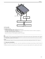
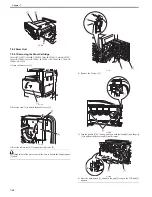
8) Release the each shutter lever [1] of the drum cartridge to remove the each
drum cartridge [2].
When Replacing the Drum Cartridge
Make sure that the shutter lever is at the Unlock position when removing the
drum cartridge. Removing the drum cartridge from the main body and re-
placing it with a new cartridge when the shutter lever is not at the Unlock po-
sition will cause malfunction in opening the drum cartridge shutter. As a
result, toner cannot flow from the hopper assembly to the drum cartridge
causing overflowed toner to spatter inside the body.
When the drum cartridge has been removed while the shutter lever is not at
the Unlock position, put the cartridge back and then position the shutter lever
to the Unlock position. After that the drum cartridge can be removed.
F-7-66
7.9.3 Drum ITB Motor
7.9.3.1 Before Removing the Drum ITB Moto
0014-2630
Color iR C3380G / Color iR C2880G / Color iR C3380i / Color iR C3380 /
Color iR C2880i / Color iR C2880 / iR C3480 / iR C3480i / iR C3080 / iR
C3080i / iR C2550
1) Detach the upper rear cover.
[Detaching the Upper Rear
Cover]
2) Detach the lower rear cover.
[Detaching the Lower Rear
Cover]
3) Remove the all-night power supply PCB.
[Detaching the
All-Night Power Supply PCB]
7.9.3.2 Removing the Drum ITB Motor
0014-2631
Color iR C3380G / Color iR C2880G / Color iR C3380i / Color iR C3380 /
Color iR C2880i / Color iR C2880 / iR C3480 / iR C3480i / iR C3080 / iR
C3080i / iR C2550
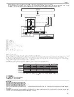
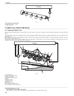
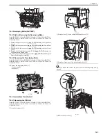
1) Remove the power supply fan 2 mount [1].
- 1 connector [2]
- 1 screw [3]
F-7-67
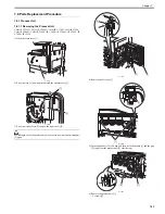
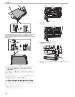
2) Disconnect the 7 connectors on the optional power supply PCB [1].
3) Disconnect the 12 connectors on the controller power supply PCB [2].
4) Remove the optional power supply/controller power supply mount [3].
- 10 wire saddles [4]
- 3 edge saddles [5]
- 1 connector [6]
- 4 screws [7]
- 2 screws [8]
[1]
[2]
[3]
[1]
[2]
[1]
[2]
[2]
[3]
[1]
Summary of Contents for CiRC2550
Page 2: ......
Page 27: ...Chapter 1 Introduction ...
Page 28: ......
Page 47: ...Chapter 1 1 18 F 1 14 ON OFF ON OFF ...
Page 70: ...Chapter 1 1 41 5 Turn on the main power switch ...
Page 79: ...Chapter 2 Installation ...
Page 80: ......
Page 85: ...Chapter 2 2 3 Not available in some regions ...
Page 134: ...Chapter 3 Basic Operation ...
Page 135: ......
Page 137: ......
Page 143: ...Chapter 4 Main Controller ...
Page 144: ......
Page 152: ...Chapter 4 4 6 F 4 6 CPU HDD ROM access to the program at time of execution ...
Page 171: ...Chapter 5 Original Exposure System ...
Page 172: ......
Page 203: ...Chapter 6 Laser Exposure ...
Page 204: ......
Page 206: ......
Page 220: ...Chapter 7 Image Formation ...
Page 221: ......
Page 277: ...Chapter 8 Pickup Feeding System ...
Page 278: ......
Page 282: ......
Page 336: ...Chapter 9 Fixing System ...
Page 337: ......
Page 339: ......
Page 357: ...Chapter 10 Externals and Controls ...
Page 358: ......
Page 362: ......
Page 366: ...Chapter 10 10 4 F 10 2 F 10 3 FM1 FM2 FM5 FM8 FM11 FM4 FM3 FM6 FM7 FM9 FM10 ...
Page 375: ...Chapter 10 10 13 F 10 10 2 Remove the check mark from SNMP Status Enabled ...
Page 376: ...Chapter 10 10 14 F 10 11 ...
Page 402: ...Chapter 11 MEAP ...
Page 403: ......
Page 405: ......
Page 452: ...Chapter 12 RDS ...
Page 453: ......
Page 455: ......
Page 464: ...Chapter 13 Maintenance and Inspection ...
Page 465: ......
Page 467: ......
Page 469: ...Chapter 13 13 2 F 13 1 8 9 1 2 3 3 5 6 7 10 11 12 13 14 4 ...
Page 474: ...Chapter 14 Standards and Adjustments ...
Page 475: ......
Page 477: ......
Page 485: ......
Page 486: ...Chapter 15 Correcting Faulty Images ...
Page 487: ......
Page 495: ...Chapter 15 15 4 F 15 2 COLOR M 1 COLOR Y C K 0 ...
Page 569: ...Chapter 15 15 78 F 15 82 J102 J107 J103 J108 J101 J109 J106 J112 J115 J113 J114 J104 J105 ...
Page 570: ...Chapter 16 Self Diagnosis ...
Page 571: ......
Page 573: ......
Page 600: ...Chapter 17 Service Mode ...
Page 601: ......
Page 603: ......
Page 712: ...Chapter 18 Upgrading ...
Page 713: ......
Page 715: ......
Page 746: ...Chapter 19 Service Tools ...
Page 747: ......
Page 749: ......
Page 752: ...APPENDIX ...
Page 774: ......