


Chapter 10
10-1
10.1 Control Panel
10.1.1 Overview
0013-8651
Color iR C3380G / Color iR C2880G / Color iR C3380i / Color iR C3380 / Color iR C2880i / Color iR C2880 / iR C3480 / iR C3480i / iR C3080 / iR C3080i / iR
C2550
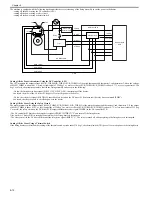
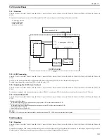
The machine's control panel consists of the following PCBs, LCD, and touch panel, each offering the functions that follow:
- LCD display function
- contrast adjustment
- touch switch input
- hardware key input
F-10-1
10.1.2 LCD Processing
0013-8653
Color iR C3380G / Color iR C2880G / Color iR C3380i / Color iR C3380 / Color iR C2880i / Color iR C2880 / iR C3480 / iR C3480i / iR C3080 / iR C3080i / iR
C2550
The CPU on the main controlled PCB sends data (display data) to the control panel CPU PCB as instructed by the program.
The data is sent through the control panel PCB to reach the color LCD.
10.1.3 Adjusting the LCD Screen Contrast
0013-8654
Color iR C3380G / Color iR C2880G / Color iR C3380i / Color iR C3380 / Color iR C2880i / Color iR C2880 / iR C3480 / iR C3480i / iR C3080 / iR C3080i / iR
C2550
The machine is equipped with a density adjustment volume (VR6801) on its keypad PCB for use by the user to adjust the contrast of the LCD screen.
10.1.4 Control Panel CPU
0013-8655
Color iR C3380G / Color iR C2880G / Color iR C3380i / Color iR C3380 / Color iR C2880i / Color iR C2880 / iR C3480 / iR C3480i / iR C3080 / iR C3080i / iR
C2550
- Monitoring the Key Inputs
It communicates the keypad and function key inputs to the CPU on the main controller PCB.
- Monitoring the Touch Panel Input
It communicates the key inputs made on the touch panel to the CPU on the main controller PCB.
- Controlling the Buzzer Sound
- Controlling the Control Panel LED
MEMO:
The color LCD is driven by the main controller, and the control panel CPU PCB serves to relay the drive signals.
10.2 Counters
10.2.1 Overview
0013-8656
Color iR C3380G / Color iR C2880G / Color iR C3380i / Color iR C3380 / Color iR C2880i / Color iR C2880 / iR C3480 / iR C3480i / iR C3080 / iR C3080i / iR
C2550
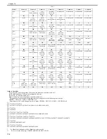
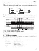
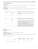
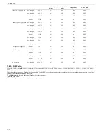
The machine is equipped with counters that indicate the counts of output according to types of printers. These counters are indicated in response to a press on the
Check key on the control panel, and they operate as follows (as set at time of shipment from the factory):
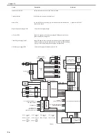
Main controller PCB
Control panel CPU PCB
touch panel
Color LCD
Keypad PCB
Control panel
inverter PCB
J1015A,J1015B
J2117A,J2117B
J1114
J1110,J1111
J6891,J6892
J2137
J1112
J1113
Control panel
Summary of Contents for CiRC2550
Page 2: ......
Page 27: ...Chapter 1 Introduction ...
Page 28: ......
Page 47: ...Chapter 1 1 18 F 1 14 ON OFF ON OFF ...
Page 70: ...Chapter 1 1 41 5 Turn on the main power switch ...
Page 79: ...Chapter 2 Installation ...
Page 80: ......
Page 85: ...Chapter 2 2 3 Not available in some regions ...
Page 134: ...Chapter 3 Basic Operation ...
Page 135: ......
Page 137: ......
Page 143: ...Chapter 4 Main Controller ...
Page 144: ......
Page 152: ...Chapter 4 4 6 F 4 6 CPU HDD ROM access to the program at time of execution ...
Page 171: ...Chapter 5 Original Exposure System ...
Page 172: ......
Page 203: ...Chapter 6 Laser Exposure ...
Page 204: ......
Page 206: ......
Page 220: ...Chapter 7 Image Formation ...
Page 221: ......
Page 277: ...Chapter 8 Pickup Feeding System ...
Page 278: ......
Page 282: ......
Page 336: ...Chapter 9 Fixing System ...
Page 337: ......
Page 339: ......
Page 357: ...Chapter 10 Externals and Controls ...
Page 358: ......
Page 362: ......
Page 366: ...Chapter 10 10 4 F 10 2 F 10 3 FM1 FM2 FM5 FM8 FM11 FM4 FM3 FM6 FM7 FM9 FM10 ...
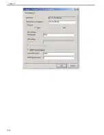
Page 375: ...Chapter 10 10 13 F 10 10 2 Remove the check mark from SNMP Status Enabled ...
Page 376: ...Chapter 10 10 14 F 10 11 ...
Page 402: ...Chapter 11 MEAP ...
Page 403: ......
Page 405: ......
Page 452: ...Chapter 12 RDS ...
Page 453: ......
Page 455: ......
Page 464: ...Chapter 13 Maintenance and Inspection ...
Page 465: ......
Page 467: ......
Page 469: ...Chapter 13 13 2 F 13 1 8 9 1 2 3 3 5 6 7 10 11 12 13 14 4 ...
Page 474: ...Chapter 14 Standards and Adjustments ...
Page 475: ......
Page 477: ......
Page 485: ......
Page 486: ...Chapter 15 Correcting Faulty Images ...
Page 487: ......
Page 495: ...Chapter 15 15 4 F 15 2 COLOR M 1 COLOR Y C K 0 ...
Page 569: ...Chapter 15 15 78 F 15 82 J102 J107 J103 J108 J101 J109 J106 J112 J115 J113 J114 J104 J105 ...
Page 570: ...Chapter 16 Self Diagnosis ...
Page 571: ......
Page 573: ......
Page 600: ...Chapter 17 Service Mode ...
Page 601: ......
Page 603: ......
Page 712: ...Chapter 18 Upgrading ...
Page 713: ......
Page 715: ......
Page 746: ...Chapter 19 Service Tools ...
Page 747: ......
Page 749: ......
Page 752: ...APPENDIX ...
Page 774: ......