


Chapter 7
7-37
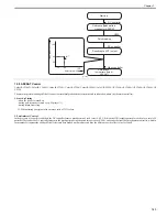
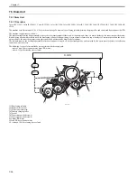
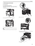
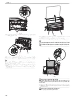
scraping spring and the toner feed screw are activated, and the toner on the hopper assembly is feed to the drum unit.
The above operations are controlled by the DC controller. The DC controller computes the amount of toner used from the ATR control results, uses this
information to judge how long the toner refill motor should be driven, and thus supplies the required amount of refill toner to the drum.
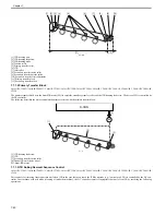
F-7-43
[1] Stirring plate
[2] Agitating plate
[3] Scraping spring
[4] Sensor flag
[5] Toner feed screw
[6] Toner feed motor drive signal
[7] Toner feed motor error detection signal
[8] toner container
[9] drum unit
[10] Hopper assembly
M8 and M11: Toner feed motor
PS3 through PS6: Toner feed level sensor
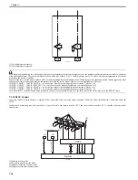
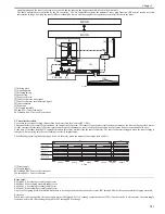
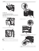
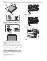
2. Toner level detection
To execute correct toner feeding, this machine has a toner feed level sensor (PS3~PS6).
This sensor detects the sensor flag mounted on the shaft of the feed screw. This sensor flag executes reciprocating movement by the drive of the toner feed motor.
It is the structure that the toner feed screw rotates and the specified amount of toner is fed to the drum unit when the sensor flag moves back and forth once.
At the time of the toner feeding, DC controller monitors this sensor while driving the toner feed motor. The toner feed motor is stopped when the toner feeding is
completed. By executing this, the toner feeding is correctly implemented.
The following is a timing chart depicting when 4 A4 full-color prints are made (with an image ratio of 40%):
F-7-44
[1] Drum supply
[2] Hopper supply
PS3 through PS6: Toner feed level sensor
M8 through M11: Toner feed motor
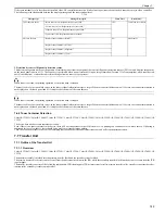
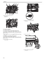
Error code:
E025-0000: Y developing assembly supply error
E025-0001: M developing assembly supply error
E025-0002: C developing assembly supply error
E025-0003: Bk developing assembly supply error
Any of the foregoing errors is identified when there is no change in the output of a specific sensor (PS3 through PS6) used for a particular developing assembly.
Reference:
While toner is being supplied, the toner supply motor (M8 through M11) is rotating counterclockwise (CCW). In other words, if all is normal, the toner supply
feedscrew will rotate, thus causing the output of PS3 through PS6 to change.
CW
CCW
[10]
M8 11
[8]
[9]
[1]
[2]
[4]
PS3 PS6
[5]
[6]
[7]
M-CON
D-CON
[3]
250ms
250ms
250ms
250ms
500ms
100ms
[1]
[2]
PS3 PS6
CL1 CL4
M8 M11
M2 M3
CCW
CW
Summary of Contents for CiRC2550
Page 2: ......
Page 27: ...Chapter 1 Introduction ...
Page 28: ......
Page 47: ...Chapter 1 1 18 F 1 14 ON OFF ON OFF ...
Page 70: ...Chapter 1 1 41 5 Turn on the main power switch ...
Page 79: ...Chapter 2 Installation ...
Page 80: ......
Page 85: ...Chapter 2 2 3 Not available in some regions ...
Page 134: ...Chapter 3 Basic Operation ...
Page 135: ......
Page 137: ......
Page 143: ...Chapter 4 Main Controller ...
Page 144: ......
Page 152: ...Chapter 4 4 6 F 4 6 CPU HDD ROM access to the program at time of execution ...
Page 171: ...Chapter 5 Original Exposure System ...
Page 172: ......
Page 203: ...Chapter 6 Laser Exposure ...
Page 204: ......
Page 206: ......
Page 220: ...Chapter 7 Image Formation ...
Page 221: ......
Page 277: ...Chapter 8 Pickup Feeding System ...
Page 278: ......
Page 282: ......
Page 336: ...Chapter 9 Fixing System ...
Page 337: ......
Page 339: ......
Page 357: ...Chapter 10 Externals and Controls ...
Page 358: ......
Page 362: ......
Page 366: ...Chapter 10 10 4 F 10 2 F 10 3 FM1 FM2 FM5 FM8 FM11 FM4 FM3 FM6 FM7 FM9 FM10 ...
Page 375: ...Chapter 10 10 13 F 10 10 2 Remove the check mark from SNMP Status Enabled ...
Page 376: ...Chapter 10 10 14 F 10 11 ...
Page 402: ...Chapter 11 MEAP ...
Page 403: ......
Page 405: ......
Page 452: ...Chapter 12 RDS ...
Page 453: ......
Page 455: ......
Page 464: ...Chapter 13 Maintenance and Inspection ...
Page 465: ......
Page 467: ......
Page 469: ...Chapter 13 13 2 F 13 1 8 9 1 2 3 3 5 6 7 10 11 12 13 14 4 ...
Page 474: ...Chapter 14 Standards and Adjustments ...
Page 475: ......
Page 477: ......
Page 485: ......
Page 486: ...Chapter 15 Correcting Faulty Images ...
Page 487: ......
Page 495: ...Chapter 15 15 4 F 15 2 COLOR M 1 COLOR Y C K 0 ...
Page 569: ...Chapter 15 15 78 F 15 82 J102 J107 J103 J108 J101 J109 J106 J112 J115 J113 J114 J104 J105 ...
Page 570: ...Chapter 16 Self Diagnosis ...
Page 571: ......
Page 573: ......
Page 600: ...Chapter 17 Service Mode ...
Page 601: ......
Page 603: ......
Page 712: ...Chapter 18 Upgrading ...
Page 713: ......
Page 715: ......
Page 746: ...Chapter 19 Service Tools ...
Page 747: ......
Page 749: ......
Page 752: ...APPENDIX ...
Page 774: ......


