


Chapter 14
14-3
14.3 Image Formation System
14.3.1 After Replacing the Secondary Transfer Roller
0014-3128
Color iR C3380G / Color iR C2880G / Color iR C3380i / Color iR C3380 /
Color iR C2880i / Color iR C2880 / iR C3480 / iR C3480i / iR C3080i / iR
C2550
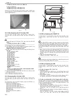
Upon replacement to the new secondary transfer outer roller, attachment of
the rubber component of the secondary transfer roller onto the ITB belt caus-
es a white spot image.
In order to prevent this, at replacing the secondary transfer outer roller to the
new one, coating of toner onto the surface of the roller is required.
When replacing the secondary transfer outer roller, execute the service mode
below:
COPIER > FUNCTION > TNR-COAT
Coating of the Y toner onto the secondary transfer roller
In case the white spot image occurred after replacing the secondary transfer
roller, clean the ITB unit.
Initial settings / registration > adjustment / cleaning > cleaning within the
main body
14.4 Fixing System
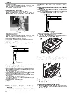
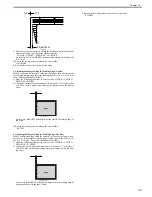
14.4.1 Confirming of the nip width
0014-3631
Color iR C3380G / Color iR C2880G / Color iR C3380i / Color iR C3380 /
Color iR C2880i / Color iR C2880 / iR C3480 / iR C3480i / iR C3080i / iR
C2550
Executed the following item of the service mode, and measure the nip width.
COPIER>FUNCTION>FIXING>NIP-CHK
*:The sheet stops temporarily at the fixing unit and it is delivered.
Standard of the nip width
Center part: 8mm or more
Difference of right and left edge: 1mm or less
14.5 Electrical Components
14.5.1 After Replacing the Reader Controller PCB
0014-3118
Color iR C3380G / Color iR C2880G / Color iR C3380i / Color iR C3380 /
Color iR C2880i / Color iR C2880 / iR C3480 / iR C3480i / iR C3080i / iR
C2550
- Before replacing the reader controller PCB, be sure to generate the latest
P-PRINT printout.
- If you carry out the power ON and the copier returns to the standby
condition after the controller circuit PCB replacement, turn ON/OFF the
power supply once again.
<if you are initializing the RAM of the reader controller without replacing
the PCB>
- Using the SST, upload the reader controller backup data; after
initializing the RAM, download the data, thus eliminating the need for the
following adjustment.
1. Reader Unit-Related Adjustment
1) Using the SST, download the latest system software (R-CON).
2) Make the following selections in service mode: COPIER>FUNC-
TION>CLEAR>R-CON; then, press the OK key to initialize the RAM.
Thereafter, turn off and then on the main power.
3) Enter the appropriate values using the following service mode items:
a. standard white plate white level data
COPIER>ADJUST>CCD>W-PLT-X,Y,Z
b. offset value against color displacement for copyboard glass (copyboard
cover)
COPIER>ADJUST>CCD>BOOK-RG
c. offset value against color displacement for copyboard glass (ADF)
COPIER>ADJUST>CCD>DF-RG
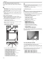
F-14-7
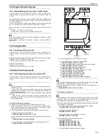
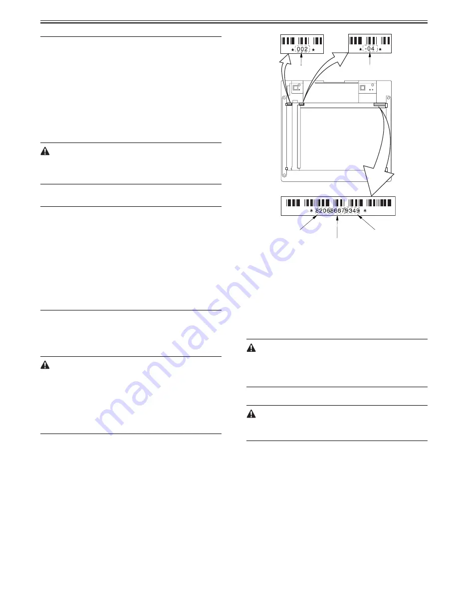
d. service label (behind reader unit left cover) values
d-1. CIS read position adjustment (fixed reading)
COPIER>ADJUST>ADJ-XY>ADJ-X
d-2. main scanning direction position adjustment (fixed reading)
COPIER>ADJUST>ADJ-XY>ADJ-Y
d-3. shading position adjustment (fixed reading)
COPIER>ADJUST>ADJ-XY>ADJ-S
d-4. sub scanning direction color displacement correction
COPIER>ADJUST>CCD>CCDU-RG
d-5. main/sub scanning direction MTF value
COPIER>ADJUST>CCD>MTF-MG,SG
d-6. auto gradation correction target value
COPIER>ADJUST>PASCAL>OFST-P-Y,M,C,K
If the value of the following was not 0 before the replacement of the reader
controller PCB: COPIER>OPTION>BODY>CCD-LUT.
Set a value other than '0' once again, and make the following adjustments us-
ing the D-10 Chart.
COPIER>FUNCTION>CCD>LUT-ADJ2
2. ADF-Related Adjustment
The machine keeps ADF-related service mode data in the RAM of the reader
controller; as such, you will have to make the appropriate adjustments if you
have replaced the reader controller or initialized the RAM.
1) Enter the values indicated in the P-PRINT printout you have previously
generated for the following:
a. main scanning direction position adjustment (stream reading)
COPIER>ADJSUT>ADJ-XY>ADJ-Y-DF
b. original stop position adjustment
FEEDER>ADJSUT>DOCST
c. original feed speed (magnification) adjustment
FEEDER>ADUST>LA-SPEED
2) Make adjustments using the following items:
a. tray width adjustment
FEEDER>FUNCTION>TRY-A4
FEEDER>FUNCTION>TRY-A5R
FEEDER>FUNCTION>TRY-LTR
FEEDER>FUNCTION>TRY-LTRR
b. CIS read position adjustment (stream reading)
W- P LT- X
W- P LT- Y
W- P LT- Z
D F - R G
B O O K - R G
Summary of Contents for CiRC2550
Page 2: ......
Page 27: ...Chapter 1 Introduction ...
Page 28: ......
Page 47: ...Chapter 1 1 18 F 1 14 ON OFF ON OFF ...
Page 70: ...Chapter 1 1 41 5 Turn on the main power switch ...
Page 79: ...Chapter 2 Installation ...
Page 80: ......
Page 85: ...Chapter 2 2 3 Not available in some regions ...
Page 134: ...Chapter 3 Basic Operation ...
Page 135: ......
Page 137: ......
Page 143: ...Chapter 4 Main Controller ...
Page 144: ......
Page 152: ...Chapter 4 4 6 F 4 6 CPU HDD ROM access to the program at time of execution ...
Page 171: ...Chapter 5 Original Exposure System ...
Page 172: ......
Page 203: ...Chapter 6 Laser Exposure ...
Page 204: ......
Page 206: ......
Page 220: ...Chapter 7 Image Formation ...
Page 221: ......
Page 277: ...Chapter 8 Pickup Feeding System ...
Page 278: ......
Page 282: ......
Page 336: ...Chapter 9 Fixing System ...
Page 337: ......
Page 339: ......
Page 357: ...Chapter 10 Externals and Controls ...
Page 358: ......
Page 362: ......
Page 366: ...Chapter 10 10 4 F 10 2 F 10 3 FM1 FM2 FM5 FM8 FM11 FM4 FM3 FM6 FM7 FM9 FM10 ...
Page 375: ...Chapter 10 10 13 F 10 10 2 Remove the check mark from SNMP Status Enabled ...
Page 376: ...Chapter 10 10 14 F 10 11 ...
Page 402: ...Chapter 11 MEAP ...
Page 403: ......
Page 405: ......
Page 452: ...Chapter 12 RDS ...
Page 453: ......
Page 455: ......
Page 464: ...Chapter 13 Maintenance and Inspection ...
Page 465: ......
Page 467: ......
Page 469: ...Chapter 13 13 2 F 13 1 8 9 1 2 3 3 5 6 7 10 11 12 13 14 4 ...
Page 474: ...Chapter 14 Standards and Adjustments ...
Page 475: ......
Page 477: ......
Page 485: ......
Page 486: ...Chapter 15 Correcting Faulty Images ...
Page 487: ......
Page 495: ...Chapter 15 15 4 F 15 2 COLOR M 1 COLOR Y C K 0 ...
Page 569: ...Chapter 15 15 78 F 15 82 J102 J107 J103 J108 J101 J109 J106 J112 J115 J113 J114 J104 J105 ...
Page 570: ...Chapter 16 Self Diagnosis ...
Page 571: ......
Page 573: ......
Page 600: ...Chapter 17 Service Mode ...
Page 601: ......
Page 603: ......
Page 712: ...Chapter 18 Upgrading ...
Page 713: ......
Page 715: ......
Page 746: ...Chapter 19 Service Tools ...
Page 747: ......
Page 749: ......
Page 752: ...APPENDIX ...
Page 774: ......


