


Chapter 17
17-2
17.1.2 Entering or selecting service modes
0013-8679
Color iR C3380G / Color iR C2880G / Color iR C3380i / Color iR C3380 / Color iR C2880i / Color iR C2880 / iR C3480 / iR C3480i / iR C3080 / iR C3080i / iR
C2550
If you want to execute a machine operation using a service mode item, be sure to disconnect all cables from an external controller or a network before starting
service mode. Particularly, if you are using a FUNCTION (operation/inspection) mode item, the arrival of a print job from an external source can cause the machine
to malfunction, leading to damage.
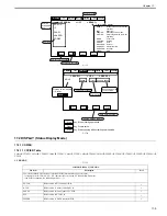
1) Press the asterisk key "
" on the control panel.
2) Press the 2 and 8 keys of the keypad at the same time.
3) Press the asterisk key "
" on the control panel.
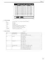
In response to the foregoing key operations, the machine will bring up the following Initial screen:
F-17-3
17.1.3 Exiting service modes
0013-8680
Color iR C3380G / Color iR C2880G / Color iR C3380i / Color iR C3380 / Color iR C2880i / Color iR C2880 / iR C3480 / iR C3480i / iR C3080 / iR C3080i / iR
C2550
A press on the Reset key will bring back the Service Mode Initial screen.
Another press on the Reset key will end service mode, and bring back the User screen (standard screen).
If you used service mode (ADJUST, FUNCTION, OPTION), be sure to turn off and then on the main power switch after ending service mode.
17.1.4 Back-up of service mode
0013-8681
Color iR C3380G / Color iR C2880G / Color iR C3380i / Color iR C3380 / Color iR C2880i / Color iR C2880 / iR C3480 / iR C3480i / iR C3080 / iR C3080i / iR
C2550
At time of shipment from the factory, all machines are adjusted individually, and adjustment values are recorded in their respective service labels.
If you have replaced the reader controller PCB or the DC controller PCB, or if you have initialized the RAM, the adjustment values (for ADJUST and OPTION)
will return to their default settings. If there has been any change in a service mode item, be sure to update its setting indicated on the service label. As necessary,
make use of the space in the service label (as when recording an item not found on the label).
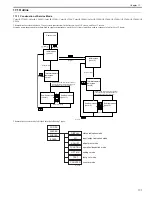
- Service Label for the Reader Controller PCB (behind the left cover [1] of the reader unit)
COPIER
FEEDER
SORTER
ADF's service mode
only when installed.
only if installed; the absence
of a mode for a sorter prevents
the indication of the notation.
BOARD
Optional board's service mode
only if installed
Copier's service mode
Sorter's or finisher's service mode
Summary of Contents for CiRC2550
Page 2: ......
Page 27: ...Chapter 1 Introduction ...
Page 28: ......
Page 47: ...Chapter 1 1 18 F 1 14 ON OFF ON OFF ...
Page 70: ...Chapter 1 1 41 5 Turn on the main power switch ...
Page 79: ...Chapter 2 Installation ...
Page 80: ......
Page 85: ...Chapter 2 2 3 Not available in some regions ...
Page 134: ...Chapter 3 Basic Operation ...
Page 135: ......
Page 137: ......
Page 143: ...Chapter 4 Main Controller ...
Page 144: ......
Page 152: ...Chapter 4 4 6 F 4 6 CPU HDD ROM access to the program at time of execution ...
Page 171: ...Chapter 5 Original Exposure System ...
Page 172: ......
Page 203: ...Chapter 6 Laser Exposure ...
Page 204: ......
Page 206: ......
Page 220: ...Chapter 7 Image Formation ...
Page 221: ......
Page 277: ...Chapter 8 Pickup Feeding System ...
Page 278: ......
Page 282: ......
Page 336: ...Chapter 9 Fixing System ...
Page 337: ......
Page 339: ......
Page 357: ...Chapter 10 Externals and Controls ...
Page 358: ......
Page 362: ......
Page 366: ...Chapter 10 10 4 F 10 2 F 10 3 FM1 FM2 FM5 FM8 FM11 FM4 FM3 FM6 FM7 FM9 FM10 ...
Page 375: ...Chapter 10 10 13 F 10 10 2 Remove the check mark from SNMP Status Enabled ...
Page 376: ...Chapter 10 10 14 F 10 11 ...
Page 402: ...Chapter 11 MEAP ...
Page 403: ......
Page 405: ......
Page 452: ...Chapter 12 RDS ...
Page 453: ......
Page 455: ......
Page 464: ...Chapter 13 Maintenance and Inspection ...
Page 465: ......
Page 467: ......
Page 469: ...Chapter 13 13 2 F 13 1 8 9 1 2 3 3 5 6 7 10 11 12 13 14 4 ...
Page 474: ...Chapter 14 Standards and Adjustments ...
Page 475: ......
Page 477: ......
Page 485: ......
Page 486: ...Chapter 15 Correcting Faulty Images ...
Page 487: ......
Page 495: ...Chapter 15 15 4 F 15 2 COLOR M 1 COLOR Y C K 0 ...
Page 569: ...Chapter 15 15 78 F 15 82 J102 J107 J103 J108 J101 J109 J106 J112 J115 J113 J114 J104 J105 ...
Page 570: ...Chapter 16 Self Diagnosis ...
Page 571: ......
Page 573: ......
Page 600: ...Chapter 17 Service Mode ...
Page 601: ......
Page 603: ......
Page 712: ...Chapter 18 Upgrading ...
Page 713: ......
Page 715: ......
Page 746: ...Chapter 19 Service Tools ...
Page 747: ......
Page 749: ......
Page 752: ...APPENDIX ...
Page 774: ......


