


Chapter 4
4-22
C3080i / iR C2550
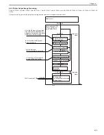
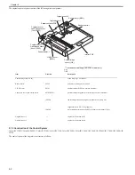
1) Detach the rear upper cover.
[Detaching the Rear Upper
Cover]
2) Remove the HDD.
[Removing the HDD]
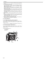
4.7.8.2 Removing the SRAM
0014-2514
Color iR C3380G / Color iR C2880G / Color iR C3380i / Color iR C3380 /
Color iR C2880i / Color iR C2880 / iR C3480 / iR C3480i / iR C3080 / iR
C3080i / iR C2550
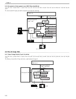
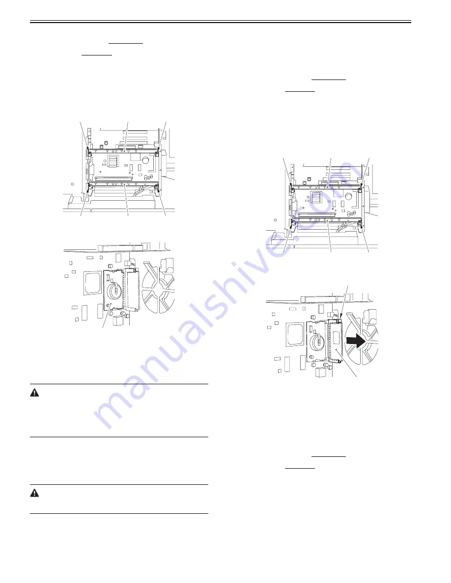
1) Remove the 2 HDD mounts [2].
- 2 screws each [1]
F-4-32
2) Remove the SRAM PCB [1].
F-4-33
4.7.8.3 When Replacing the SRAM PCB
0014-3122
Color iR C3380G / Color iR C2880G / Color iR C3380i / Color iR C3380 /
Color iR C2880i / Color iR C2880 / iR C3480 / iR C3480i / iR C3080 / iR
C3080i / iR C2550
When the SRAM PCB is replaced, all data in its memory will be lost (file-
related, user mode-related, service mode-related, history-related files). There
will be no error operation, and initialization will take place automatically.
If you pull out the SRAM PCB from machine B and mount it to machine A,
the PCB will be initialized and be rendered useless for machine A or B. Take
full care.
1) When you turn on the power after replacing the SRAM PCB, the machine
will perform automatic initialization and will indicate a message on its
panel to the effect that you are to turn off and then on the power switch
found on its right side. Follow the message and turn off and then on the
machine.
2) Using service mode, initialize the RAM.
COPIER> FUNCTION> CLEAR> MN-CON
Before starting the work, be sure to inform the user that all image data stored
in the Box will be lost and obtain his/her consent.
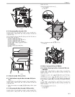
4.7.9 Boot ROM PCB
4.7.9.1 Before Removing the Boot ROM PCB
0014-2530
Color iR C3380G / Color iR C2880G / Color iR C3380i / Color iR C3380 /
Color iR C2880i / Color iR C2880 / iR C3480 / iR C3480i / iR C3080 / iR
C3080i / iR C2550
1) Detach the rear upper cover.
[Detaching the Rear Upper
Cover]
[Removing the HDD]
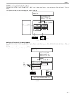
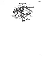
4.7.9.2 Removing the Boot ROM PCB
0014-2528
Color iR C3380G / Color iR C2880G / Color iR C3380i / Color iR C3380 /
Color iR C2880i / Color iR C2880 / iR C3480 / iR C3480i / iR C3080 / iR
C3080i / iR C2550
1) Remove the 2 HDD mounts [2]
- 2 screws each [1]
F-4-34
2) Press the PCB release button [1] to remove the Boot ROM PCB [2].
F-4-35
4.7.10 Image Memory (SDRAM)
4.7.10.1 Before Removing the Image Memory (SDRAM)
PCB
0014-2532
Color iR C3380G / Color iR C2880G / Color iR C3380i / Color iR C3380 /
Color iR C2880i / Color iR C2880 / iR C3480 / iR C3480i / iR C3080 / iR
C3080i / iR C2550
1) Detach the rear upper cover.
[Detaching the Rear Upper
Cover]
[Removing the HDD]
4.7.10.2 Removing the Image Memory (SDRAM) PCB
0014-2531
Color iR C3380G / Color iR C2880G / Color iR C3380i / Color iR C3380 /
Color iR C2880i / Color iR C2880 / iR C3480 / iR C3480i / iR C3080 / iR
C3080i / iR C2550
1) Remove the 2 HDD mounts [2].
- 2 screws each [1]
[1]
[1]
[2]
[1]
[1]
[2]
[1]
[1]
[1]
[2]
[1]
[1]
[2]
[2]
[1]
Summary of Contents for CiRC2550
Page 2: ......
Page 27: ...Chapter 1 Introduction ...
Page 28: ......
Page 47: ...Chapter 1 1 18 F 1 14 ON OFF ON OFF ...
Page 70: ...Chapter 1 1 41 5 Turn on the main power switch ...
Page 79: ...Chapter 2 Installation ...
Page 80: ......
Page 85: ...Chapter 2 2 3 Not available in some regions ...
Page 134: ...Chapter 3 Basic Operation ...
Page 135: ......
Page 137: ......
Page 143: ...Chapter 4 Main Controller ...
Page 144: ......
Page 152: ...Chapter 4 4 6 F 4 6 CPU HDD ROM access to the program at time of execution ...
Page 171: ...Chapter 5 Original Exposure System ...
Page 172: ......
Page 203: ...Chapter 6 Laser Exposure ...
Page 204: ......
Page 206: ......
Page 220: ...Chapter 7 Image Formation ...
Page 221: ......
Page 277: ...Chapter 8 Pickup Feeding System ...
Page 278: ......
Page 282: ......
Page 336: ...Chapter 9 Fixing System ...
Page 337: ......
Page 339: ......
Page 357: ...Chapter 10 Externals and Controls ...
Page 358: ......
Page 362: ......
Page 366: ...Chapter 10 10 4 F 10 2 F 10 3 FM1 FM2 FM5 FM8 FM11 FM4 FM3 FM6 FM7 FM9 FM10 ...
Page 375: ...Chapter 10 10 13 F 10 10 2 Remove the check mark from SNMP Status Enabled ...
Page 376: ...Chapter 10 10 14 F 10 11 ...
Page 402: ...Chapter 11 MEAP ...
Page 403: ......
Page 405: ......
Page 452: ...Chapter 12 RDS ...
Page 453: ......
Page 455: ......
Page 464: ...Chapter 13 Maintenance and Inspection ...
Page 465: ......
Page 467: ......
Page 469: ...Chapter 13 13 2 F 13 1 8 9 1 2 3 3 5 6 7 10 11 12 13 14 4 ...
Page 474: ...Chapter 14 Standards and Adjustments ...
Page 475: ......
Page 477: ......
Page 485: ......
Page 486: ...Chapter 15 Correcting Faulty Images ...
Page 487: ......
Page 495: ...Chapter 15 15 4 F 15 2 COLOR M 1 COLOR Y C K 0 ...
Page 569: ...Chapter 15 15 78 F 15 82 J102 J107 J103 J108 J101 J109 J106 J112 J115 J113 J114 J104 J105 ...
Page 570: ...Chapter 16 Self Diagnosis ...
Page 571: ......
Page 573: ......
Page 600: ...Chapter 17 Service Mode ...
Page 601: ......
Page 603: ......
Page 712: ...Chapter 18 Upgrading ...
Page 713: ......
Page 715: ......
Page 746: ...Chapter 19 Service Tools ...
Page 747: ......
Page 749: ......
Page 752: ...APPENDIX ...
Page 774: ......


