


Chapter 17
17-71
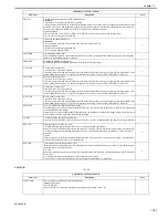
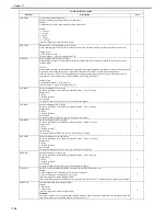
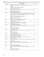
ANIM-SW
Prohibition against switching error or jam screen display during operation of MEAP application
Even when COPIER>OPTION>BODY>MEAP-DSP has been set to "1," the display is transferred to the standard screen
in order to display a warning when an error, jam or alarm has occurred.
When this item has been set to "1," the transfer of the screen to the standard screen when an error, jam or alarm has
occurred is prohibited, and a warning urging the user to contact a service technician appears on the MEAP screen.
Settings
0: The warning screen is displayed.
1: The warning screen is not displayed.
[Factory setting/value after clearing RAM: 0]
2
HDD-TMP
Use it to set a level of temperature to serve as a reference for detecting a low temperature error.
Caution!
The new setting will not be valid until the power switch has been turned off and then on again.
Settings: 0 to 30 deg C
[Factory default/After RAM clear: 2]
2
HDD-TIM
Use it to set the time interval allowed before a low temperature error is identified
Caution!
The new setting will not be valid until the power switch has been turned off and then on again.
Settings: 0 to 200 min
[Factory default/After RAM clear: 10]
2
HDD-SW
Use it to enable/disable E code indication of a low temperature error
Caution!
The new setting will not be valid until the power switch has been turned off and then on again
Settings
0: do not indicate
1: indicate
[Factory default/After RAM clear: 0]
2
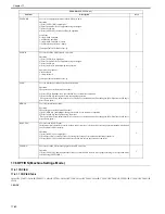
MEAP-SSL
Use it to set an HTTPS port for MEAP.
Sets a port for the HTTPS server to use SSL in the MEAP HTTP.
Setting range: 1 to 65535
[Factory default/After RAM clear: 8443]
2
DH-TMG
Setting up a threshold for the accumulated number of outputs for the Dhalf control sequence operation trigger.
Control
If the fixing unit is lower than a specified temperature when the machine is turned on or recovered from the sleep mode,
use this mode to make automatic full adjustments during initial multiple rotations.
At this time, the Dhalf control is performed only if the number of outputs accumulated since the last Dhalf control
exceeds the value specified in this Service Mode.
Changing the timing of or canceling the Dhalf control (according to the number of accumulated outputs) by using this
mode can reduce the downtime in the morning. (A measure for a complaint about the downtime in the morning)
Meanwhile, there is a possibility that gray scale (half-tone image) might be degraded when the Dhalf control is cancelled.
With regard to the accumulated number of outputs, a small-size copy is regarded as 1 count, and a large-size copy is
regarded as 2 counts.
When the Dhalf control is performed first thi
2
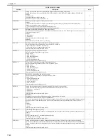
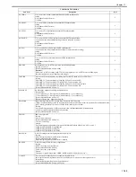
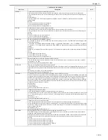
MIX-FLG
Use it to select an image field flag (for image synthesis).
Selects the image processing method which is performed when a combined image cannot be compressed at a certain
compression ratio on the main controller side.
Setting value
0: Image processing equivalent to the PDL character mode
1: Image processing equivalent to the PDL photo mode
2: Image processing equivalent to the SCAN character mode
3: Image processing equivalent to the SCAN photo mode
[Factory default/After RAM clear: 0]
2
KSIZE-SW
Paper size (K size) switch for China
This switch allows iR series scanner controllers to support K size paper detection and display.
When the switch is set to ON = 1 for MODEL-SZ = (AB type) destinations, the operation switches to allow K size paper
recognition and detection to be performed with document detection, paper selection screen and APS type, etc. The
following types of K size paper are available.
- 8K: 270mm x 390 mm
- 16K: 270mm x 195 mm
Setting values
0: OFF (K size paper not handled)
1: ON (K size paper handled)
[Factory settings and after RAM clear: 0]
2
LPD-PORT
LPD port number setting
Reference:
LPD port: Port number of the network for TCP/IP communication when initiating network printing.
Setting range: 1 to 65535
[Factory setting/value after clearing RAM: 515]
2
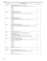
ORG-A4R
Setting of special sheet sizes which cannot be recognized when ADF is used
This enables images to be formed properly by setting from the service mode the special sheet sizes which cannot be
recognized when documents are fed from ADF.
When ADF has detected A4-R in a machine for an inch/AB series market, A4-R is converted into a document size which
has been set in the service mode, and the images are formed using the post-conversion document size.
Settings
0: The document size is converted into A4-R.
1: The document size is converted into FOLIO-R.
[Factory setting/value after clearing RAM: 0]
2
COPIER>OPTION>BODY
Sub item
Description
level.
Summary of Contents for CiRC2550
Page 2: ......
Page 27: ...Chapter 1 Introduction ...
Page 28: ......
Page 47: ...Chapter 1 1 18 F 1 14 ON OFF ON OFF ...
Page 70: ...Chapter 1 1 41 5 Turn on the main power switch ...
Page 79: ...Chapter 2 Installation ...
Page 80: ......
Page 85: ...Chapter 2 2 3 Not available in some regions ...
Page 134: ...Chapter 3 Basic Operation ...
Page 135: ......
Page 137: ......
Page 143: ...Chapter 4 Main Controller ...
Page 144: ......
Page 152: ...Chapter 4 4 6 F 4 6 CPU HDD ROM access to the program at time of execution ...
Page 171: ...Chapter 5 Original Exposure System ...
Page 172: ......
Page 203: ...Chapter 6 Laser Exposure ...
Page 204: ......
Page 206: ......
Page 220: ...Chapter 7 Image Formation ...
Page 221: ......
Page 277: ...Chapter 8 Pickup Feeding System ...
Page 278: ......
Page 282: ......
Page 336: ...Chapter 9 Fixing System ...
Page 337: ......
Page 339: ......
Page 357: ...Chapter 10 Externals and Controls ...
Page 358: ......
Page 362: ......
Page 366: ...Chapter 10 10 4 F 10 2 F 10 3 FM1 FM2 FM5 FM8 FM11 FM4 FM3 FM6 FM7 FM9 FM10 ...
Page 375: ...Chapter 10 10 13 F 10 10 2 Remove the check mark from SNMP Status Enabled ...
Page 376: ...Chapter 10 10 14 F 10 11 ...
Page 402: ...Chapter 11 MEAP ...
Page 403: ......
Page 405: ......
Page 452: ...Chapter 12 RDS ...
Page 453: ......
Page 455: ......
Page 464: ...Chapter 13 Maintenance and Inspection ...
Page 465: ......
Page 467: ......
Page 469: ...Chapter 13 13 2 F 13 1 8 9 1 2 3 3 5 6 7 10 11 12 13 14 4 ...
Page 474: ...Chapter 14 Standards and Adjustments ...
Page 475: ......
Page 477: ......
Page 485: ......
Page 486: ...Chapter 15 Correcting Faulty Images ...
Page 487: ......
Page 495: ...Chapter 15 15 4 F 15 2 COLOR M 1 COLOR Y C K 0 ...
Page 569: ...Chapter 15 15 78 F 15 82 J102 J107 J103 J108 J101 J109 J106 J112 J115 J113 J114 J104 J105 ...
Page 570: ...Chapter 16 Self Diagnosis ...
Page 571: ......
Page 573: ......
Page 600: ...Chapter 17 Service Mode ...
Page 601: ......
Page 603: ......
Page 712: ...Chapter 18 Upgrading ...
Page 713: ......
Page 715: ......
Page 746: ...Chapter 19 Service Tools ...
Page 747: ......
Page 749: ......
Page 752: ...APPENDIX ...
Page 774: ......