


Chapter 17
17-40
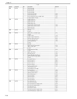
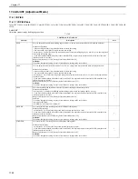
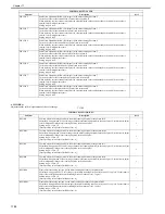
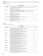
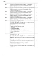
SIGG-C
Display the gain value for the C-color toner density standard signal for ATR control.
Display the C-color patch level when executing ATR-INIT, which is executed at PCRG initialization.
Use this item to determine a cause of a density fault.
When replacing the DCON PCB, enter the unique ATR-INIT value for each PCRG.
Setting range: 0 to 255
[Factory setting value/Value after RAM clear: 0]
1
SIGG-K
Display the gain value for the K-color toner density standard signal for ATR control.
Display the K-color patch level when executing ATR-INIT, which is executed at PCRG initialization.
Use this item to determine a cause of a density fault.
When replacing the DCON PCB, enter the unique ATR-INIT value for each PCRG.
Setting range: 0 to 255
[Factory setting value/Value after RAM clear: 0]
1
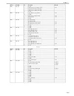
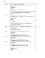
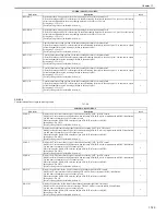
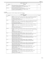
T-SPLY-Y
Adjust the toner supply amount (Y-color)
Adjustment method:
When executing RAM clear for the DC controller PCB or replacing the DC controller PCB, enter the value indicated on
the service label.
Adjustment range: -3 to 3
[Factory setting value/Value after RAM clear: 0]
2
T-SPLY-M
Adjust the toner supply amount (M-color)
Adjustment method:
When executing RAM clear for the DC controller PCB or replacing the DC controller PCB, enter the value indicated on
the service label.
Adjustment range: -3 to 3
[Factory setting value/Value after RAM clear: 0]
2
T-SPLY-C
Adjust the toner supply amount (C-color)
Adjustment method:
When executing RAM clear for the DC controller PCB or replacing the DC controller PCB, enter the value indicated on
the service label.
Adjustment range: -3 to 3
[Factory setting value/Value after RAM clear: 0]
2
T-SPLY-K
Adjust the toner supply amount (K-color)
Adjustment method:
When executing RAM clear for the DC controller PCB or replacing the DC controller PCB, enter the value indicated on
the service label.
Adjustment range: -3 to 3
[Factory setting value/Value after RAM clear: 0]
2
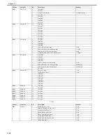
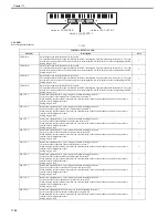
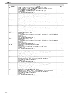
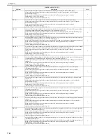
DMAX-K
Adjust the offset for the target value of K-color density control.
Adjustment method:
Set the offset value for the target value of K-color density control at D-MAX control.
Setting range: -8 to 8
[Factory setting value/Value after RAM clear: 0]
2
P-TG-Y
Adjust the offset for the target value (Y-color) of ATR control.
Add the offset to the ATR patch TGT which was determined at initialization, and change the T/D ratio.
Changing the setting value by 1 will add the offset value by 30 levels to ATR patch TGT.
Use this item for low/high density or fogging images.
Setting range: -4 to 4
[Factory setting value/Value after RAM clear: 0]
2
P-TG-M
Adjust the offset for the target value (M-color) of ATR control.
Add the offset to the ATR patch TGT which was determined at initialization, and change the T/D ratio.
Changing the setting value by 1 will add the offset value by 30 levels to ATR patch TGT.
Use this item for low/high density or fogging images.
Setting range: -4 to 4
[Factory setting value/Value after RAM clear: 0]
2
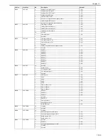
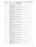
P-TG-C
Adjust the offset for the target value (C-color) of ATR control.
Add the offset to the ATR patch TGT which was determined at initialization, and change the T/D ratio.
Changing the setting value by 1 will add the offset value by 30 levels to ATR patch TGT.
Use this item for low/high density or fogging images.
Setting range: -4 to 4
[Factory setting value/Value after RAM clear: 0]
2
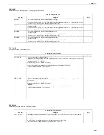
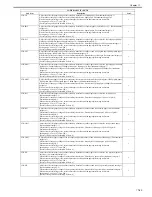
P-TG-K
Adjust the offset for the target value (Bk-color) of ATR control.
Add the offset to the ATR patch TGT which was determined at initialization, and change the T/D ratio.
Changing the setting value by 1 will add the offset value by 30 levels to ATR patch TGT.
Use this item for low/high density or fogging images.
Setting range: -4 to 4
[Factory setting value/Value after RAM clear: 0]
2
COPIER>ADJUST>DENS
Sub item
Description
level.
Summary of Contents for CiRC2550
Page 2: ......
Page 27: ...Chapter 1 Introduction ...
Page 28: ......
Page 47: ...Chapter 1 1 18 F 1 14 ON OFF ON OFF ...
Page 70: ...Chapter 1 1 41 5 Turn on the main power switch ...
Page 79: ...Chapter 2 Installation ...
Page 80: ......
Page 85: ...Chapter 2 2 3 Not available in some regions ...
Page 134: ...Chapter 3 Basic Operation ...
Page 135: ......
Page 137: ......
Page 143: ...Chapter 4 Main Controller ...
Page 144: ......
Page 152: ...Chapter 4 4 6 F 4 6 CPU HDD ROM access to the program at time of execution ...
Page 171: ...Chapter 5 Original Exposure System ...
Page 172: ......
Page 203: ...Chapter 6 Laser Exposure ...
Page 204: ......
Page 206: ......
Page 220: ...Chapter 7 Image Formation ...
Page 221: ......
Page 277: ...Chapter 8 Pickup Feeding System ...
Page 278: ......
Page 282: ......
Page 336: ...Chapter 9 Fixing System ...
Page 337: ......
Page 339: ......
Page 357: ...Chapter 10 Externals and Controls ...
Page 358: ......
Page 362: ......
Page 366: ...Chapter 10 10 4 F 10 2 F 10 3 FM1 FM2 FM5 FM8 FM11 FM4 FM3 FM6 FM7 FM9 FM10 ...
Page 375: ...Chapter 10 10 13 F 10 10 2 Remove the check mark from SNMP Status Enabled ...
Page 376: ...Chapter 10 10 14 F 10 11 ...
Page 402: ...Chapter 11 MEAP ...
Page 403: ......
Page 405: ......
Page 452: ...Chapter 12 RDS ...
Page 453: ......
Page 455: ......
Page 464: ...Chapter 13 Maintenance and Inspection ...
Page 465: ......
Page 467: ......
Page 469: ...Chapter 13 13 2 F 13 1 8 9 1 2 3 3 5 6 7 10 11 12 13 14 4 ...
Page 474: ...Chapter 14 Standards and Adjustments ...
Page 475: ......
Page 477: ......
Page 485: ......
Page 486: ...Chapter 15 Correcting Faulty Images ...
Page 487: ......
Page 495: ...Chapter 15 15 4 F 15 2 COLOR M 1 COLOR Y C K 0 ...
Page 569: ...Chapter 15 15 78 F 15 82 J102 J107 J103 J108 J101 J109 J106 J112 J115 J113 J114 J104 J105 ...
Page 570: ...Chapter 16 Self Diagnosis ...
Page 571: ......
Page 573: ......
Page 600: ...Chapter 17 Service Mode ...
Page 601: ......
Page 603: ......
Page 712: ...Chapter 18 Upgrading ...
Page 713: ......
Page 715: ......
Page 746: ...Chapter 19 Service Tools ...
Page 747: ......
Page 749: ......
Page 752: ...APPENDIX ...
Page 774: ......